3
$\begingroup$

I am reading the famous Feynman Lectures, Volume I, the section about electromagnetic radiation. After defining what radiation is (the part of the electric field induced by the acceleration of a charged particle), he describes an experiment to measure this part of the field/the radiation.

Essentially the radiation is induced by two wires where electrons move up and down, and a similar construction is used for measuring the radiation:

[...] an instrument to detect an electric field, and the instrument we use is the same thing—a pair of wires like $A$ and $B$! If an electric field is applied to such a device, it will produce a force which will pull the electrons up on both wires or down on both wires. This signal is detected by means of a rectifier mounted between $A$ and $B$, and a tiny, fine wire carries the information into an amplifier, where it is amplified so we can hear the audiofrequency tone with which the radiofrequency is modulated. [...]

For the setup please see the image in the linked source. Then he explains what is happening when we line up the measuring device with the field:

[...] Secondly, the formula says that the electric field should be perpendicular to $r$ and in the plane of $G$ and $r$; so if we put $D$ at $1$ but rotate it $90^{\circ}$, we should get no signal. [...]

Okay, this seems somehow ideally to assume the measuring device just measures the movement in concordance with the alignement of the two wires. But is this feasible? The wires also have some thickness, and I think still electrons are moving if we turn the device $D$ as described, but perpendicular to how the wires are arranged, so the measuring device should measure something. Or could it be arranged that this motion does not trigger any response?

Hopefully I have understood it correctly, but could anybody explain if, when my understanding is correct, such a measurement device could be built? I am also unsure what Prof Feynman means with the rectifier measuring the electron movement?

$\endgroup$

2 Answers 2

2
$\begingroup$

There will be a tiny signal when the apparatus is rotated: let's say the antenna (because that's what it is) is 1m long and the frequency is about what would allow an electron to go from one end to the other during one half-oscillation. If you rotate the apparatus, the distance the electron can travel is say 1mm: the diameter of the wire. It will travel that in a very small time, which will be a tiny part of the half-oscillation, and it will get stuck to the wall, so to speak: it cannot go any further. As more and more electrons do that, they will set up a field opposite to the radiation field and when that field becomes equal in magnitude to the radiation field, no more electrons will move for the rest of that half-oscillation. So instead of having a sinusoidal motion for the electrons sloshing back and forth (as you have in the normal case), you'll have a sinusoid with most of the peak chopped off: the electrons will move a tiny bit and then get stuck. When the radiation field reverses, they'll move in the opposite direction, and get stuck. The signal won't be zero, but it will be very small compared to the full sinusoid you get when the apparatus is not rotated.

$\endgroup$
1
2
$\begingroup$

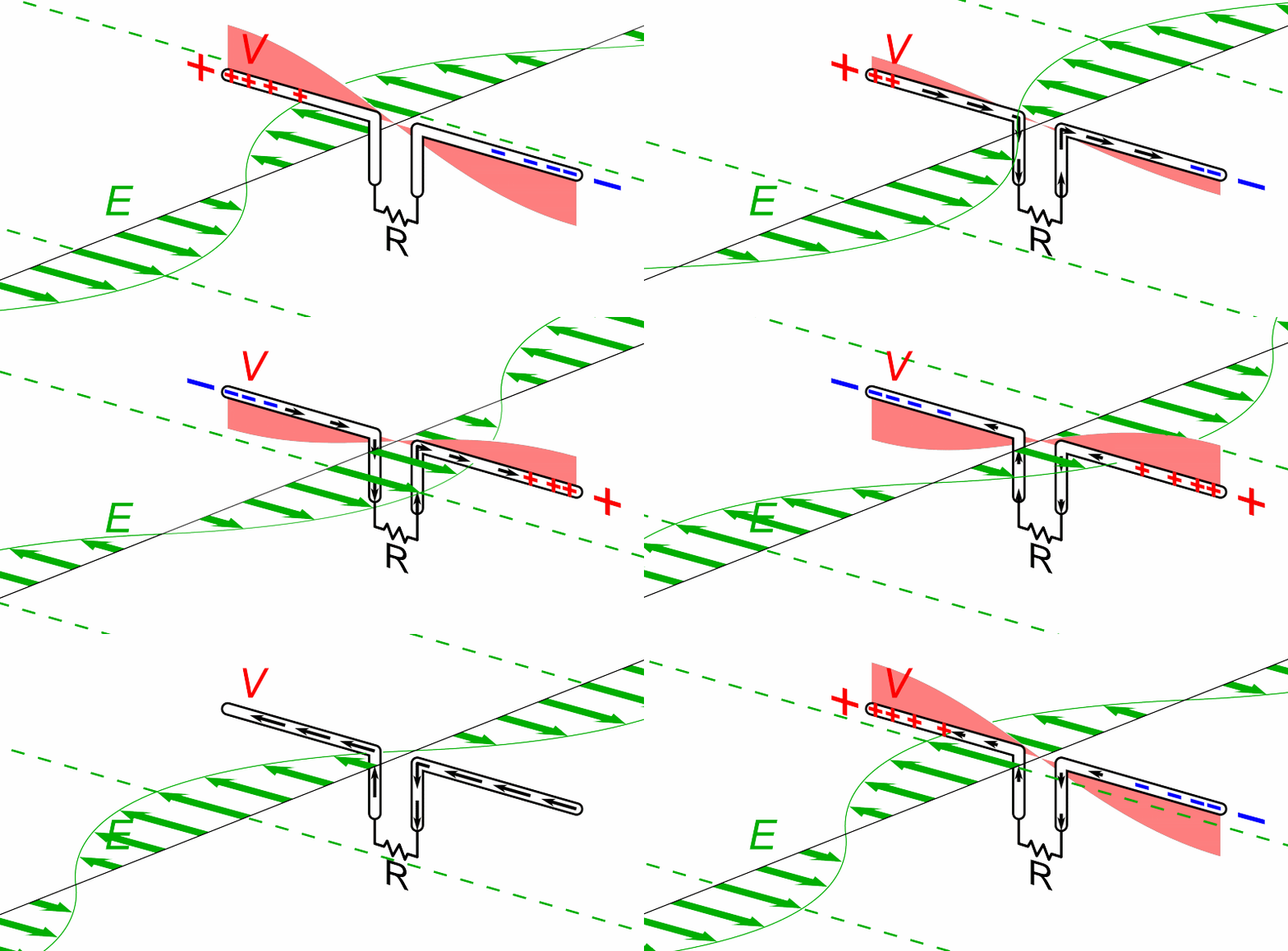
Here is a nice animation which illustrates what happens if an incoming plane polarised oscillating electric field is incident on a dipole antenna.
The electrons in the dipole antenna are forced to oscillate and hence a alternating voltage is developed across the resistor.

enter image description here

If the length of the dipole is chosen correctly, the length being related to the wavelength of the electric field, there is a resonance effect and so the alternating current through the resistor can be large enough to detect.
The animated diagram tries to show this by having what looks like a standing wave produced in the antenna. You can now imagine that putting a diode in place of, or in series with, the resistor as suggested by Feynman will produce a unidirectional current/voltage which could be amplified.
In practice one can improve the arrangement by first making sure that as much power as possible is transferred from the antenna to the detecting circuit by careful design of the detecting circuit which will then contain the diode.

Now rotate the electric field through $90^\circ$ and there will be an oscillating voltage across a diameter of the wire but its magnitude will be considerably smaller than with the electric field being the the same plane as the antenna.
As Feynman pointed out this will give a zero reading at the detector end.

You have suggested rotating the detector circuit around so that the voltage across a diameter of the wire could be measured.
Even if you had such a detecting circuit, because the diameter of the antenna would be so different from the the wavelength of the electric field, the amplitude of forced oscillation of the elections would be very small leading to a minute voltage to be detected.

$\endgroup$

Your Answer

By clicking “Post Your Answer”, you agree to our terms of service and acknowledge you have read our privacy policy.

Not the answer you're looking for? Browse other questions tagged or ask your own question.