0
$\begingroup$

I understand standard RC circuits perfectly well, but I don't understand what the $R$ term in the capacitor charge equation for RC circuits represents in more complex situations. The actual problem I'm solving is below: enter image description here
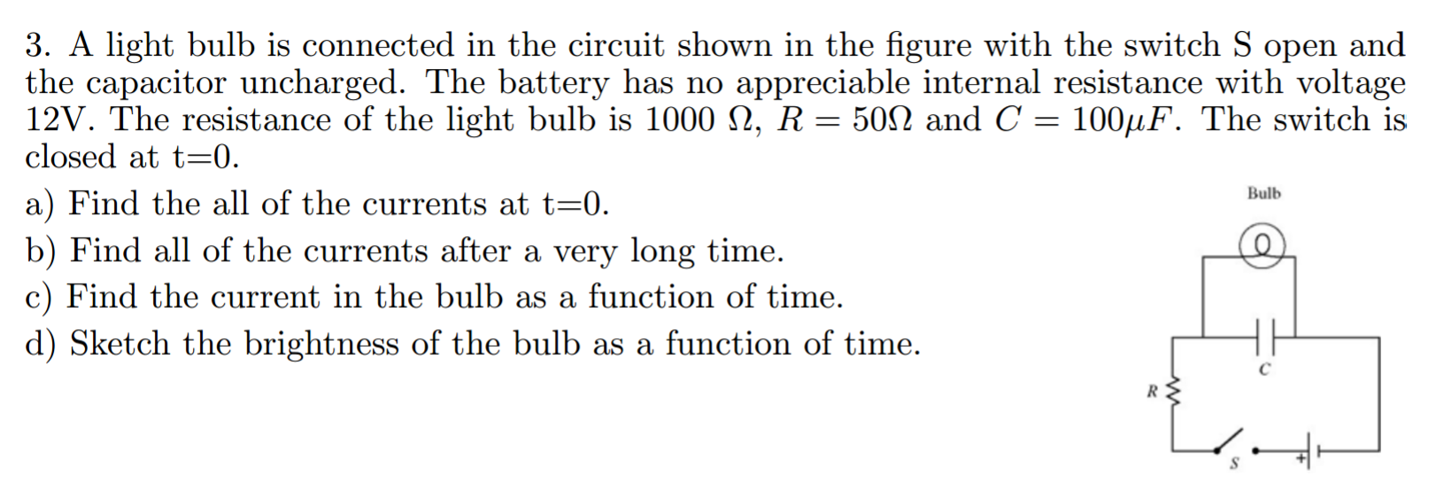
Part C is the part that I'm finding tricky. I know that $\Delta V$ across the bulb is equal to $\Delta V$ across the resistor, and I know that:

$$I_c = \frac{Ve^{\frac{-T}{RC}}}{R}$$

I also know that $\frac{I_c}{V_c}$ is going to be the effective resistance of the capacitor, and that I can find this using the equation above. From here, I know that I can proceed to easily work out all the voltages and currents.

The roadblock I'm running into is figuring out what R is in the formula for $I_c$. I know that it's the resistance in the circuit, but the resistance of what part of the circuit? My instinct is to say "just the resistance of the resistor" but I know this isn't true because changing the resistance in the lightbulb (e.g. making it zero or infinite) would obviously affect the rate at which the capacitor charged. At the same time, there is no obvious way that I can see to account for the resistance of the lightbulb nor a way to create an equivalent circuit that is more straight-forward.

Thank you for you help!

$\endgroup$
2
  • $\begingroup$ Read Thévenin's theorem $\endgroup$ Commented Feb 10, 2017 at 3:11
  • 1
    $\begingroup$ If I remember correctly, you can find the equivalent resistance in a capacitor by switching off all the independent generator of tension (they are now just wires) and of current (now equivalent to interrupted wires). Then close the switch S and substitute the capacitor with a test generator (either of current or of tension): given the tension, you have to evaluate the current through it, or vice versa. This should give you the R you have to use in your exponential function. $\endgroup$
    – JackI
    Commented Feb 10, 2017 at 6:33

1 Answer 1

0
$\begingroup$

Talked to some other people and eventually worked out something that predicts actual results with accuracy. Essentially, by screwing around with the mentioned equation, you can get:

$$V_{t} = V_{max} e^{\frac{-t}{RC}}$$

Where R is the series resistance. You can think of the parallel circuit with the resistor and capacitor as being sort of like a modified capacitor with a lower capacitance, so the resistance (or lack thereof) from the light bulb causes the $V_{max}$ on the capacitor to change (you can easily work out the new $V_{max}$, I won't get into it). From here, solving the problem is elementary. I will update this so it's a better answer after my midterms.

$\endgroup$

Your Answer

By clicking “Post Your Answer”, you agree to our terms of service and acknowledge you have read our privacy policy.

Not the answer you're looking for? Browse other questions tagged or ask your own question.