1
$\begingroup$

The following problem is of my interest. Consider a bar of length $L$ with two fulcrums, each a distance $d$ away from the end of the bar (see Figure).

$\hspace{5cm}$
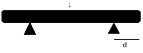
Let us view this bar as three pieces, one is to the left of the left fulcrum, one is in between the two fulcrums, and one is to the right of the right fulcrum. My goal is to determine the distance $d$ in such a way so that the torque on each of these three pieces is minimized. That is, I seek $d$ such that the sagging of each piece is as minimal as possible. Furthermore, let us consider the torques acting at the center of mass of each of the three pieces, and let's assume a uniform mass density for the bar.

I have come up with the following torque equations and answer, however, I am skeptical of my own work! Any help on this would be greatly appreciated.

Let $\tau_m$ be the torque acting on the middle piece and $\tau_s$ be the torque acting on the side pieces. (Note that the torques on the two side pieces are equal). Also note that the mass of each piece is the total mass $m$ multiplied by the ratio of the length of the piece to the total length $L$. We have,

$$\tau_m=\frac{mg}{L}\left[\left(L-2d\right)^2-d^2\right],\mathrm{and}$$ $$\tau_s=\frac{mg}{2L}\left[d^2-\left(L-2d\right)^2\right].$$

To me, the common sense solution was to have $\tau_m$ and $\tau_s$ equal. This leads to $d=\frac{8-\sqrt(26)}{12} L.$ However, such a value results in a negative side torque, that is $\tau_s$ points upward (negative direction). This clearly doesn't seem right as it means the middle piece is sagging pretty noticeably.

Please tell me if I need to provide any further clarifications, and thanks in advance for all the help!

$\endgroup$

2 Answers 2

3
$\begingroup$

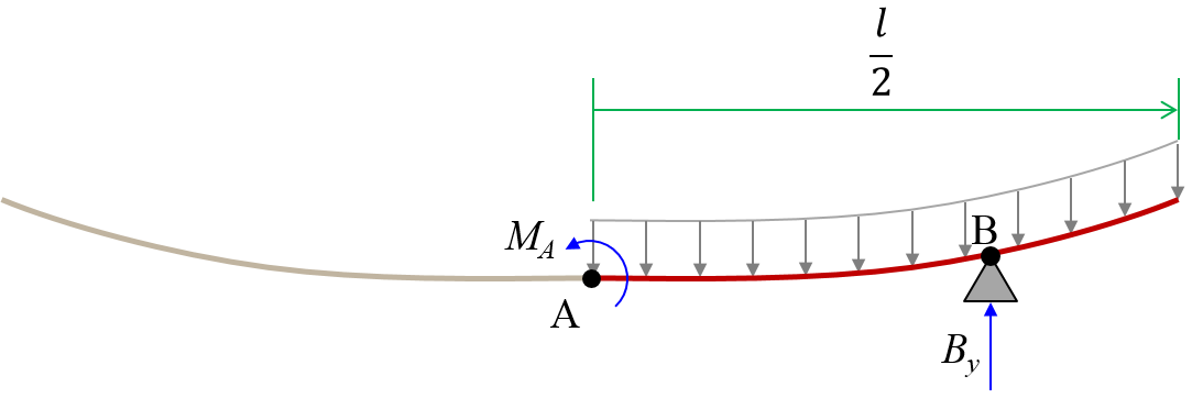
First off you can look at half the bar, with a symmetry constraint. From the middle (I call point A) the fulcrum (point B) is located a distance $b$ such that $d =\frac{\ell}{2}-b$. The beam has uniform weight distribution $w = \frac{m g}{\ell}$ and we consider the weight supported by the fulcrum force $B_y$.

fbd

Using standard beam theory* I calculated the shape of the beam in two sections. From the middle A to the fulcrum B

$$ y_1 = -w \frac{2 x^4+3 \ell x^2 (\ell-4 b)-b^2 (2 b^2-12 b \ell + 3 \ell^2)}{48 E I} $$

and from the fulcrum B to the end

$$ y_2 = w \frac{2 x^4 - 4 \ell x^3 +3 \ell^2 x^2-12 b^2 \ell x - b^2 (2 b^2 -16 b \ell+3\ell^2)}{48 E I}$$

where $x$ is the horizontal position from the center.

This means the sag at the center is $$\delta_A =-w \frac{b^2(2 b^2-12 b \ell+3 \ell^2)}{48 E I}$$ and at the end point $$\delta_E = -w \frac{16 b^4-128 b^3 \ell+72 b^2 \ell^2-3 \ell^4}{384 E I}$$

Minimal sag is when both parts sag the same $\delta_A = \delta_E$ which happens when $$\boxed{b = \frac{\ell}{2} - \ell \sin\left( \frac{1}{3} \sin^{-1} \left( \frac{5}{8} \right) \right) \approx 0.277 \ell}$$


  1. Find the fulcrum location that makes the center deflection zero: $$b = \left(3 - \frac{\sqrt{30}}{2} \right) \ell \approx 0.261 \ell$$

  2. Find the fulcrum location that makes the end deflection zero: $$b = \left(\frac{5}{2}-2 \sqrt{6} \sin \left( \frac{1}{3} \tan^{-1}\left( \frac{29}{\sqrt{23}} \right) \right) \right) \ell \approx 0.286 \ell$$

  3. Find the fulcrum location that makes the slope at the fulcrum zero: $$ b = \left( \frac{3}{2} -\frac{\sqrt{6}}{2} \right) \ell \approx 0.275 \ell$$

  4. Find the fulcrum location that makes the slope at end zero: $$ b = \left( \frac{\sqrt{3}}{6} \right) \ell \approx 0.289 \ell $$

All of the configurations are very similar.


NOTES:

Standard beam theory means using statics to derive the internal shear forces $S(x)$ and moments $M(x)$ along the beam. Then find the deformation shape that fits the boundary conditions $y(b)=0$ and $y'(0)=0$ and obeys the equation $$M(x) = E I \frac{{\rm d}^2y}{{\rm d}x^2}$$

Thin slender beam with modulus of elasticity $E$ and area moment $I$

In this case I used two general shape equations with two unknown coefficients each $$\begin{align} y_1(x) & = \int\int M_1(x)\,{\rm d}x{\rm d}x + K_1 + K_2 x \\ y_2(x) & = \int \int M_2(x)\,{\rm d}x{\rm d}x + K_3 + K_4 x \end{align}$$

and solved for the coefficients using the following boundary conditions

$$\begin{cases} \frac{{\rm d}y_1(x)}{{\rm d}x} |_{x=0} = 0 & \mbox{slope is zero at center} \\ y_1(x)|_{x=b} = 0 &\mbox{no deflection at fulcrum} \\ y_2(x)|_{x=b} = y_1(x)|_{x=b} &\mbox{match deflection on both segments at fulcrum} \\ \frac{{\rm d}y_2(x)}{{\rm d}x}|_{x=b} = \frac{{\rm d}y_1(x)}{{\rm d}x}|_{x=b} &\mbox{match slope on both segments at fulcrum} \\ \end{cases}$$

which is 4 equations for 4 unknowns ($K_1$, $K_2$, $K_2$ and $K_4$).

In summary: internal moments (torques) define the curvature of the beam (2nd derivative) and the curvature needs to be integrated twice to get the deflection.

PS. great question

$\endgroup$
3
  • $\begingroup$ Omg! Thank you so much for putting all this effort into this. I truly appreciate it. Thank you. $\endgroup$
    – Ptheguy
    Commented Dec 22, 2016 at 22:47
  • $\begingroup$ Outstanding answer. The only thing that could be described more clearly is that deflection and torque are not the same thing (OP seems to be conflating them). Your treatment shows this but it bears stating explicitly, I think. $\endgroup$
    – Floris
    Commented Dec 23, 2016 at 2:56
  • 1
    $\begingroup$ I have added a little more explanation on how you go about solving beam problems like this. $\endgroup$ Commented Dec 23, 2016 at 16:15
1
$\begingroup$

I don't think there is there any torque on the middle piece it is supported at both ends. This clouds your question, it's not clear from what point you imagine that $$T_m$$ acts. If you split it into 2 equal elements, there will be 3 points of interest, $$T_s$$ at each end and $$T_m$$ in the middle, the torque in the centre of the longest span of the bridge will be modelled.

When you balance a rod on a fulcrum the net torque is 0.

As I think you already guessed balancing each half of the bridge on a central fulcrum will balance the torque. i.e. $$d=L/4$$

Do consider the stress on each picece - whether each piece is rigid and strong enough to bear the opposing torsional forces on opposite ends.

$\endgroup$
7
  • $\begingroup$ Thank you for the info. Are you saying that theres no torque on the middle piece, the L-2d piece? I thought there would be, considering the torque acts at its center of mass. $\endgroup$
    – Ptheguy
    Commented Dec 22, 2016 at 18:04
  • $\begingroup$ Also, what I'm not sure about is whether simply balancing the torque which would be $d=L/4$ results, too, in a minimized torque on the three pieces. $\endgroup$
    – Ptheguy
    Commented Dec 22, 2016 at 18:28
  • $\begingroup$ With three pieces, each considered rigid, the middle piece is supported at both ends. There is no pivot point about which it be inclined to turn? If you say it's not rigid, then you can model a deformation due to a torque in it's center - but this is easier to model if you split it in two. $\endgroup$
    – JMLCarter
    Commented Dec 23, 2016 at 2:54
  • $\begingroup$ with $d=L/4$ intuitively think that each end is balancing half of the middle of the bridge. Balancing = cancelling out the torque, minimising it, $\endgroup$
    – JMLCarter
    Commented Dec 23, 2016 at 2:56
  • $\begingroup$ If you are interested in deformation and stress see ja72 answer $\endgroup$
    – JMLCarter
    Commented Dec 23, 2016 at 2:59

Your Answer

By clicking “Post Your Answer”, you agree to our terms of service and acknowledge you have read our privacy policy.

Not the answer you're looking for? Browse other questions tagged or ask your own question.