5
$\begingroup$

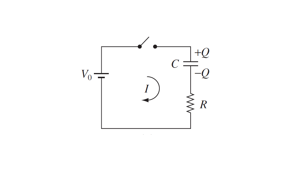
In the picture below, we are charging up the capacitor, by connecting it (and the resistor to a battery of voltage $V_0$, at time $t = 0$). In terms of what is happening physicially, how would you interpret the given equation $$V_0 = \frac{Q}{C} + IR?$$

Given that the potential difference accross the battery is $V_0$, and it charges the capacitor (which then has it's own potential difference $\frac{Q}{C}$), which produces an electric field along the conductors (wires) in a different direction to that of the battery, would it be correct to say that $V_0 - \frac{Q}{C}$ is then the net potential difference accross the battery which drives the current $I$. Hence using ohms law we have $V_0 - \frac{Q}{C} = IR$? Is this what is happening in this equation, or is it at least close?

Thanks.

Circuit with battery, capacitor and resistor

$\endgroup$

3 Answers 3

5
$\begingroup$

In effect, yes, that's about right. The equation is the result of applying Kirchhoff's voltage law to the circuit. This law states that the sum of the potential differences across each of the components of a given loop in a circuit should sum to zero.

In this case we have three components, the battery, the capacitor, and the resistor. The voltage across the battery is given as $V_0$. The voltage across a capacitor at any instant is equal to $\frac{Q}{C}$. And lastly, the voltage across the resistor can be expressed as $IR$. You can imagine starting the loop at the battery, at which point the potential difference is high. Then as you move around the circuit, the capacitor and the resistor work together to 'use up' the potential difference. In this way you can see that the capacitor and resistor potential differences should have the opposite sign to the battery voltage. Then, by the voltage law, we have

$ V_0 - \frac{Q}{C} - IR = 0 $

$\endgroup$
3
$\begingroup$

$V_0−\frac QC=IR$? Is this what is happening in this equation, or is it at least close?

Yes, naturally, this is just a rearranging of the equation you have set up. Nothing is wrong with this.

But you have to distinguish current from voltage.

  • There is a voltage (a potential difference) from the positive to the negative terminal of the battery. This voltage is the "push" that tries to push charges around the circuit. It "pushes" constantly - but that doesn't mean that any charges necessarily are moving...

  • The current in this circuit changes until the capacitor is fully charge - after which it is 0! No current can flow if there is a hole in the circuit - a capacitor is a hole in a circuit. But this is only the case when the capacitor is fully charged, because...

    • Initially, the current "doesn't know" that there is a hole. Electrons flow from one capacitor plate towards the battery's positive terminal, and electrons flow from the negative terminal towards the other capacitor plate. They move (current flows) as if the circuit is closed.
    • Pretty soon they reach the end and can't move further. Electrons gather up at the lower capacitor plate and acculumate here. The charge $-Q$ built up on this lower plate, induced the exact same charge $+Q$ of opposite sign on the other plate, because they are so close. The accumulating charges set up a counter-working electric field, growing stronger and stronger as more charges arrive.
    • At some point this counter-working electric field repels incoming electrons just as much as the negative terminal repels them. (Vice versa for the built up positive charge on the other plate attracting electrons just as much as the positive terminal does.) There is no net force on charges anymore and all charge-flow stops. This situation now looks like an open circuit.

Conclusion is that after some time (usually a very short time, but that depends on the capacitor) no more current is flowing. The equation you have shown is correct at only moment in time; just keep in mind that the values of $I$ and $Q$ change constantly (one increases and one decreases) during the charging of the capacitor. And when fully charged, $I=0$ and $Q$ is at it's maximum.

$\endgroup$
2
$\begingroup$

In terms of what is happening physically, how would you interpret the given equation $V_0 = \frac{Q}{C} + IR?$

It is a restatement of the law of conservation of energy in a form which is useful when analysing circuits.
This can be seen by multiply right though by the current $I = \frac{dQ}{dt}$ to get

$V_0 \frac{dQ}{dt}= \frac{Q}{C} \frac{dQ}{dt} + IR\frac{dQ}{dt}$

$\frac QC$ is the potential difference across the capacitor and $V_{\rm C}$ and $V_{\rm R}= IR$ the potential difference across the resistor.

$V_0 \frac{dQ}{dt}= V_{\rm C} \frac{dQ}{dt} + V_{\rm R} \frac{dQ}{dt} \quad\Rightarrow \quad V_0 \;\Delta Q= V_{\rm C}\; \Delta Q + V_{\rm R} \; \Delta Q$

I have written it out in the final form so that you can consider what happens when a small amount of charge $\Delta Q$ is taken around the circuit.

$V_0 \;\Delta Q$ represents the amount of chemical energy which has been converted into electrical energy in the battery.
$ V_{\rm C}\; \Delta Q$ represents the amount of electrical energy which is stored as electric potential energy in the electric field within the capacitor.
$V_{\rm R} \; \Delta Q$ represents the amount of electrical energy converted into heat by the resistor.

So the electrical energy supplied by the battery is equal to the electrical energy consumed by the capacitor and the resistor.

When you solve the differential for $I$ and $Q$ you can substitute those values into your original equation and integrate each term with respect to time over the whole charging period.
You will find that half of the energy supplied by the battery is stored in the capacitor and the other half of the energy is dissipated as heat in the resistor.

$\endgroup$

Your Answer

By clicking “Post Your Answer”, you agree to our terms of service and acknowledge you have read our privacy policy.