2
$\begingroup$

I'm confused about the application of Faraday's Law in to situations with a circuit made of two loops that enclose two different changing magnetic fluxes. Which of the two is correct?

  1. The emf in each loop depends only on the changing magnetic flux enclosed in that loop.
  2. The emf in each loop depends both on the changing magnetic flux enclosed in that loop and also on the changing flux enclosed by the surrounding loops.

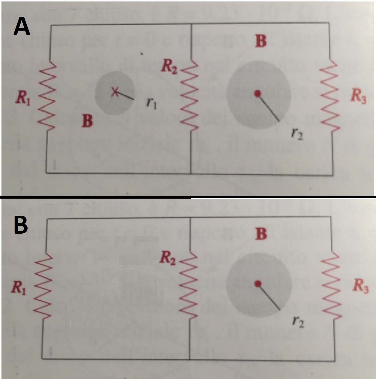
I'll made an example to show the two options. Consider the circuit made of two loops.

In case A each encloses a different solenoid, where magnetic field $B$ changes in time (and is directed in two different ways).

In case B only one of the loop encloses a changing magnetic flux, since there is no left solenoid.

enter image description here

In case A, according to 1., the current in the left loop should depend only on the magnetic field of the left solenoid.

And in case B, the total emf in the left loop should be zero since there is no changing magnetic flux enclosed by left loop, that is $$\textrm{emf}_{\mathrm{left \, loop}}=\oint_{\mathrm{left \,\, loop}} E_{\mathrm{induced}} \cdot \mathrm dl =-\frac{\mathrm d}{\mathrm dt} \Phi_\textrm{enclosed}=0$$

Nevertheless in both cases one branch (the one with $R_2$) is in common between the two loops and there the emf should be affected also by the right solenoid (and be nonzero in case $B$). This leads to contradiction with things said above.

So is 1. or 2. correct?

$\endgroup$

2 Answers 2

6
$\begingroup$

I think that of all of Maxwell's equations, it is Faraday's law that tests you the most. But you have to remember, that it always, always, always holds. All you have to do is pick a loop.

  1. is correct. Once you have chosen your loop, forget everything else for a little while, and focus on just the loop. Here's the algorithm:

Ask yourself, is there any changing flux through my loop? If there is, that is your emf. If there isn't the emf is zero. Note however, that zero emf in a loop does not mean zero current in it.

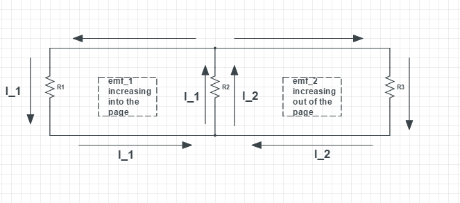
Now, find all the potential drops or rises the current in the loop undergoes and set their sum to be equal to $\frac{\mathrm d\phi}{\mathrm dt}$. During this step, I find the mesh current method most useful.

enter image description here

Now, look at just the left loop:

$$I_1R_1+(I_1+I_2)R_2=\frac{\mathrm d\phi_1}{\mathrm dt}$$

..and then at just the right loop:

$$I_2R_3+(I_1+I_2)R_2=\frac{\mathrm d\phi_2}{\mathrm dt}$$

if $I_1$ and $I_2$ are the unknowns, this is enough to solve for them.

You can do this for the "super"-loop as well:

$$I_1R_1-I_2R_3=\frac{\mathrm d\phi_1}{\mathrm dt}-\frac{\mathrm d\phi_2}{\mathrm dt}$$

All three equations give the same result.

Regarding 2., the emf in a loop is not influenced by surrounding emfs, the current in it is. In image B, there is a current in the left loop, but the sum of the potential differences that this current encounters will be zero, because the emf is zero. ie:

$$I_1R_1+(I_1+I_2)R_2=0$$

You can rewrite the other two equations as well and change $\frac{\mathrm d\phi_1}{\mathrm dt}$ to $0$ in both.

I hope this helped!

$\endgroup$
3
  • $\begingroup$ Thanks so much for this clear and complete answer! If I may, on my textbook the exercise from which the picture is taken, is solved in a way that is a bit in contrast with 1. (and that's why I asked). Consider situation A: on textbook mesh current method is used and the equation are the same ones you proposed, besides the fact that the emf considered in each loop is (minus) time derivative of magnetic flux enclosed by that loop plus $1/4$ of the time derivative of the flux in the other loop, and this is justified by saying "that's because of the common central branch". $\endgroup$
    – Sørën
    Commented Nov 1, 2016 at 14:15
  • $\begingroup$ That is (calling the left solenoid $1$ and the right solenoid $2$, and considering that the magnetic field $B$ is the same in both solenoid but varying in time) $$\begin{cases} i_1 R_1+ (i_1+i_2) R_2=\frac{dB}{dt} \pi r_1^2 + \frac{1}{4}\frac{dB}{dt} \pi r_2^2 \\ i_2 R_2+ (i_1+i_2) R_2=\frac{dB}{dt} \pi r_2^2 + \frac{1}{4}\frac{dB}{dt} \pi r_1^2 \end{cases}$$ I can't explain why this $1/4$ of the emf should be taken into account, besides the emf caused by enclosed changing magnetic flux. Could you give me any suggestions about this? $\endgroup$
    – Sørën
    Commented Nov 1, 2016 at 14:15
  • 1
    $\begingroup$ @Sørën I see no reason why this extra emf should be taken into account. $\endgroup$
    – GeeJay
    Commented Nov 2, 2016 at 6:35
-1
$\begingroup$
  1. is the correct idea. This is because, we have from maxwell's equations in differential form:

$\nabla \times \vec E$ = -$\frac{\partial \vec B}{\partial t}$

Now, using stoke's law, we know that for the curl of a vector function $F$ over the surface $S$,having boundary $B$ the following is true:

$\iint_S (\nabla \times \vec F).da$ = $\int_B \vec F . dr$

Applying this to maxwell's equation above, we have, for a chosen area $S$ and its boundary $B$:

$\iint_S (\nabla \times \vec E).da$ = -$\iint_S (\frac{\partial \vec B}{\partial t}).da$ = $\int_B \vec E . dr$ . The middle term denotes the flux (for constant area $S$ as in the example you mentioned above). Note that the flux gives the induced emf only around the chose boundary $B$.

So, to summarize, choose a circuit path, and find the flux through that boundary only. Find the emf, and hence the current in all the branches. Do this for all possible contours in the circuit. Apply the superposition principle for every branch, and hence find the net current through every part of the circuit.

$\endgroup$

Your Answer

By clicking “Post Your Answer”, you agree to our terms of service and acknowledge you have read our privacy policy.

Not the answer you're looking for? Browse other questions tagged or ask your own question.