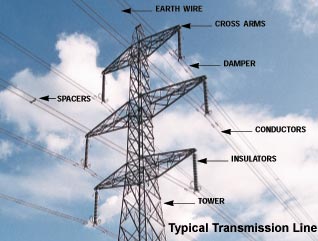
Below is a picture of a typical transmission line(about 200 kV). Is there a simple physics experiment which can be performed safely near the line, to determine the power flow direction. Or in other words: where is the generator and where a consumer.

Below is a picture of a typical transmission line(about 200 kV). Is there a simple physics experiment which can be performed safely near the line, to determine the power flow direction. Or in other words: where is the generator and where a consumer.

Actually, you don't need to measure things at two different positions along the wire to determine the power flow. You can do this with measurements taken at a single position. You must measure both current and voltage. The measuring device is built so that it rotates based on the relative phase of the current and voltage; and the direction of rotation corresponds to the direction of power flow. That's what happens in the power meter connected to your house. If you couldn't measure power flow this way it would be very hard for the electric utility to charge you for power.
EDIT: The power meter in your house of course touches the wires, but standing on the ground under a transmission line you can do something similar. You can have two pickups, a coil and a straight antenna, and you could feed them into an xy-oscilloscope. Pure reactive power should show a straight diagonal trace, and real power should show a circular loop. The problem is that you won't be able to see the direction the loop is tracing...clockwise or counterclockwise. You would need to compare the direction of rotation to a known field source, e.g. a short line you've set up purposely for calibration. You've got to make sure you're consistent with the relative physical orientation of the two pickups. In effect you're measuring the Poynting vector.
If you had two guitar amplifiers, you could amplify your pickups and feed them into an ordinary household power meter, which is already set up to convert the relative phases into an actual mechanical rotation that you can see. Of course you've still got to orient your pickups consistently and calibrate the direction of rotation against a known power flow.
Measuring T-line power flow from the ground without contact is tricky, especially near the tower. The tower is a solidly grounded structure and tends to sink the EM fields to ground, and the conductors are far from your position (high in the air). Better to move to mid-span where there is no tower and the conductors are closer to the ground. Also better to select a single-circuit power line (the photo above shows a double-circuit tower).
Voltage can be estimated with a capacitive voltage divider by using a horizontal-flat-plate capacitor on a grounded pole. The bottom plate connects to the grounded pole (is grounded), and the top plate floats at a voltage proportional to line voltage. Put a plastic sheet between them for insulation. The measurement will be corrupted by the unequal contribution of the 3 phases, but the closest phase will dominate. Be careful - this top plate can reach several hundred volts depending on the line voltage and distance from line to capacitor. It won't hurt you (too high impedance) but might damage a voltmeter.
Current can be estimated by detecting the magnetic field at ground level using a loop of wire. The varying mag field from the AC current flow in the line will couple to the coil and produce an EMF. If the coil is open circuit, this results in a 60 Hz voltage across the terminals. If it is closed circuit, the result is a 60 Hz current through the loop. Again, the value is corrupted by the 3 phases, but the closest phase will dominate. Us the right hand rule to orient your coil to determine the direction of current flow. Move the coil around to get the largest output.
Calibration is not really possible for an accurate measurement of power flow unless you have a real flow measurement to compare to, but if you are substantially closer to one outside phase than to the center and other outside phase, you should be able to compare voltage phase and current phase to determine power flow direction.
Recall that REAL Current Transformers have an orientation indication, telling you that if power is positive (voltage and current are in phase) then power flow is in a known direction. Your ground set will change power flow direction if you flip the coil around. But you can figure that out by starting with a line where you know the direction of real power flow (away from an operating generator).
If you plan to use an Arduino or other microcontroller to measure and calculate for you, be aware of the voltages and scale appropriately. A high impedance measurement device might see too high a voltage from the plate capacitor and be damaged. You can scale using a capacitive voltage divider before connecting to your measurement input. Start with a high voltage voltmeter connected to top and bottom plate set on highest AC range to get a feel for the output voltage. The indictive coil voltage is a crap-shoot - try putting a 100 ohm resistor across the open terminals and measure with a voltmeter.
Make sense?
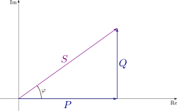
The relevant equation is that of complex power in an AC circuit:
$$\vec{S}=\frac{\vec{V} \vec{I}^{*}}{2}=\frac{V I}{2} \angle -\phi$$
This is to say, the complex power flowing through a line is equal to the complex voltage times the conjugate of the complex current divided by two. Those not familiar with AC circuits will have a tough time with the complex variables, but let's turn to the following definitions for illustration. Note that I'm going to establish voltage as the reference angle.
$$S=P+jQ$$ $$\vec{I}=I \angle \phi$$ $$\vec{V}=V \angle 0^{\circ}$$
The real power is $P$ and the imaginary power is $Q$. The interesting thing to note is that $P$ can be either negative or positive. Before applying any of this however, you must have a reference direction. You're looking at the line, you can look either right or left, you establish one of those directions as positive, and then $P$ will follow as either negative or positive and if positive, it flows in the direction you're looking.
Here is an illustration, although I think this differs in convention by the sign of $\phi$.

Now, here is what you need to establish the direction of power flow:
Exactly how you measure this is certainly the difficult part. I will defer to other answer regarding that. But provided that you do, if $\phi \in (-\pi/2,\pi/2)$ then the power flows in the positive direction and if $\phi \in (\pi/2, 3\pi/2)$ it flows in the negative direction.
When power is consumed, the voltage and current rises and fall together (with some variation due to power factor). As you consume energy from the grid the voltage generally stays the same but the current rises and falls depending on your consumption. As you reduce your demand to zero, the current falls to zero, then when you start feeding into the grid, the current becomes negative with respect to voltage (ie. 180 degrees out of phase). So to determine energy flow, you need to know the current in the wire and whether that current is negative or positive with respect to the voltage. You can do this by measuring the voltage and current at the same time (instantaneous values), then multiply them together, if the answer is negative, you are feeding into the grid, if it's positive, you are using power. How you do this is the tricky bit, a current clamp and a voltage transformer with the output calculated within a micro-controller (ie. Arduino). Could also use a current clamp and an antenna wire near the power wire with a circuit tuned to your mains frequency (measuring the emf), again results calculated via a micro-controller. Been trying to find a better/easier way to do this without contact, but as yet haven't found an easy answer? The measuring current via a current clamp is easy, but the voltage transformer and emf antenna for me have produced some erratic results.
With a high-powered rifle, shoot one of the lines in two at the middle. Observe the two ends. The one that sparks the most is the line going back to the generator.
When these power lines carry DC, I believe it is impossible to easily determine the direction of current flow.
For AC lines, it's fairly easy; one times the 60Hz signal. Use two receivers separated by long enough to get 60Hz out of phase. If the speed of light is 186,000 miles per second, and the speed of wave transmission in the lines is on that order, then a 1% phase difference will need a distance of 0.05 x 186,000 miles/second x (1/60th seconds) = 31 miles.
I learned something from the comments on this question: power companies nowadays adjust the phases of their power lines by putting capacitors and inductors in the line. They do this fairly often and their effect is to modify the relative phase. So if you do measure the field at two points near the wire, make sure that there's not a power station in between your measurements. To learn more about this, try googling "power transmission"+shunt+series
You might be interested in this article:
http://cassnewsletter.org/Volume9-Issue6/Open_Forum.html
It gives a simple rule for determining the direction of power using instantaneous values of current direction and conductor polarity.
The rule is: "In any electrical circuit, energy is flowing in the same direction as the current carriers are moving in the conductor with the same polarity as the current carriers."
Look at the negative conductor for electron flow, the positive conductor for "conventional current". Use instantaneous values for alternating current or for segments of a transmission line where standing waves are causing current reversals on segments of the line.