The confusion is because the $V$ in:
$$ W = IVt $$
is the voltage drop across the transmission line not the supply voltage.
If the power station generates some high voltage $V_0$, then at your local transformer the voltage will have fallen slightly to $V_1 = V_0 - \Delta V$ due to the resistance of the transmission lines. The voltage drop is:
$$ \Delta V = IR_{transmission} $$
where $R_{transmission}$ is the resistance of the transmission line. The power loss in the tranmission line is:
$$ W_{transmission} = I\Delta V t = I^2 R_{transmission} t $$
Response to comments:
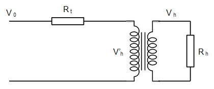
I think it's worth working out what happens quantitatively. For simplicity consider the load to be just a single house and assume there's a single transformer to reduce the transmission voltage to domestic voltage.

$V_0$ is the transmission voltage, e.g. 400kV in the UK, and $V_h$ is the voltage at the house, e.g. 240V in the UK. So the transformer separating the house from the grid has a ratio of $V_0/V_h$. I've represented the resistance of the transmission line as a single resistor, $R_t$, and we want to calculate how much power is lost in the transmission line.
Suppose the power being used by the house is $W$ - I would guess typical values for W would be a few kW - then:
$$ W = I_hV_h $$
or:
$$ I_h = \frac{W}{V_h} \tag{1} $$
For convenience we'll assume that the voltage drop across the transmission line is small so the voltage at the line side of the transformer, $V'h$, is just $V_0$. The power on both sides of the transformer is the same, so:
$$ V_0 I_0 = V_h I_h $$
Substituting for $I_h$ from equation (1) and rearranging we get:
$$ I_0 = \frac{V_h}{V_0} \frac{W}{V_h} = \frac{W}{V_0} $$
And the last step is to calculate the power dissipated in the transmission line using:
$$ W_t = I_0^2 R_t = \left(\frac{W}{V_0}\right)^2 R_t $$
The key result is that the power dissipated in the transmission line is inversely proportional to $V_0^2$. So increasing the transmission voltage $V_0$ reduces the power wasted.

