0
$\begingroup$

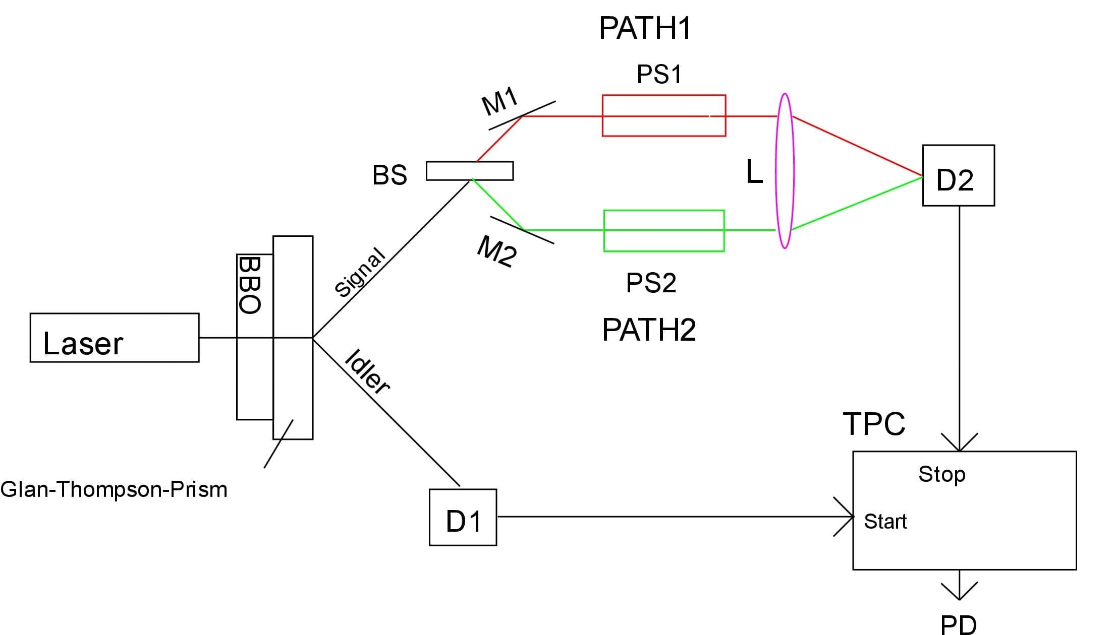
Since interference is possible with a single photon, both interfering signals of a photon, after passing a beam-splitter, arrive at the detector with a phase-shift. No upper limit of this phase-shift is known. Therefore a test setup as shown in Fig.1 should answer the question, which way the photon took.

The laser radiation is down-converted by a BBO crystal to the two entangled beams “SIGNAL” and “IDLER” which are separated by a Glan-Thompson-Prism. The “IDLER” beam is received by detector “D1” which feeds it's signal to the “Start” input of the time-to-phase converter “TPC”.

The “Signal” beam is splitted by the 50% : 50% beam-splitter “BS” into “PATH1” and “Path2” after passing the mirrors “M1” and “M2”.
In “Path1” there is the variable phase-shifter “PS1” which allows a phase shift in this path by 0 <= ps1 < 2Pi.
In “Path2” there is the phase-shifter “PS2” with ps2 = n*2Pi with n>>1. After passing the phase-shifters both signals converge on the lens “L” and interfere in it's focus on detector “D2” which feeds its signal to the “Stop” input of the “TPC”.

The level of interference and thereby the count-rate at “D1” can be determined by “PS1”.
“PS2” doesn't influence the interference at “D1” but introduces a time-delay in “Path2”.

Which path is triggering the detection of the interference-signal at “D1” can be seen at the output “PD” of the “TPC”.
If pd = ps1 it is “PATH1”.
If pd = ps2 it is “PATH2”.
If that's not true, the notion of a photon passing by “PATH1” or “PATH2” is wrong. Or am I wrong ? enter image description here FIG1 : Test setup for which-way-information
$\endgroup$
7
  • $\begingroup$ look at this answer of mine , and the edited in link at the end. I think you are confusing photonic photons with elementary particle photons physics.stackexchange.com/questions/267034/… $\endgroup$
    – anna v
    Commented Feb 9, 2021 at 15:11
  • $\begingroup$ Are there any wavelength filters in the system? $\endgroup$ Commented Feb 10, 2021 at 7:54
  • $\begingroup$ In any realization of the prosed setup the pump frequency of the laser should be blocked after the BBO crystal and depending on the S/N the down converted frequency selected by interference filters. $\endgroup$
    – werinher
    Commented Feb 11, 2021 at 21:53
  • $\begingroup$ What kind of detector is D2? In the image it looks like you focus two beams at an angle, which results in interference stripes. So I assume D2 must be spatially resolving. And how does the time-to-phase converter work? I've googled it, but it seems this is not the standard terminology. $\endgroup$
    – A. P.
    Commented Feb 14, 2021 at 8:30
  • $\begingroup$ You are right, D2 should have dimension smaller than the distance of the expected interference stripes, if a controlled interference demonstration by PS1 should be possible. The main task for D2 however is to detect any photon in the interference field, independent of the local photon count-rate. That allows to increase the sensitive area of the detector (photo multiplier or avalanche diode) to improve the detection ratio of D2/D1. The TPC is a TAC (time to amplitude converter) with additional digital signal processing or simply an electronic stopwatch. $\endgroup$
    – werinher
    Commented Feb 14, 2021 at 18:47

0

Your Answer

By clicking “Post Your Answer”, you agree to our terms of service and acknowledge you have read our privacy policy.