Bumped by Community user
added 4 characters in body
Source Link
Landau
  • 768
  • 10
  • 21

I was reading Chapter 4, on Fourier Optics, of the course notes on Photonics by Roel Baets and Günther Roelkens (Ghent University, 2009).

I am struggling with the following section:

enter image description here

4.3.5 Optical convolution processor

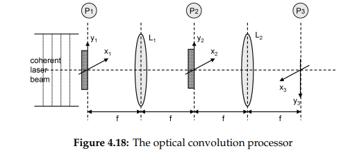
It is possible to realize, in an optical set up, a convolution between two functions $$ \left|\int \int_{-\infty}^{+\infty}g (ξ, η) h (x − ξ, y − η) dξdη\right| \tag{4.129} $$ The set up is shown in figure 4.18. The "input"-function $g$ is realized as a mask with transmittance function $g(x_1, y_1)$ and placed in plane $P_1$, which is the first focal plane of a lens $L_1$. It is normally illuminated with a monochromatic plane wave. In the second focal plane $P_2$ of this lens one obtains the Fourier transform $k_1 G(−x_2/λf, −y_2/λf)$ of $g$ (in which $k_1 =$ complex constant). In this plane $P_2$ one puts a second mask with transmittance function $$ t(x_2, y_2) = k_2 H\left(\frac{-x_2}{\lambda f},\frac{-y_2}{\lambda f}\right), \tag{4.130} $$ with $$ H (fx, fy) = F_{2D} \left\{h (x, y)\right\} \tag{4.131} $$ Behind this mask, the field is proportional to $G.H$ ; hence in the focal plane $P_3$ of the second lens $L_2$ one finds the following irradiance: $$ I (x_3, y_3) = K \left|\int \int_{-\infty}^{+\infty}g (ξ, η) h (x_3 − ξ, y_3 − η) dξdη\right|^2 \tag{4.132} $$ This kind of convolution processor can be practically realized by inserting in the planes $P_1$ and $P_2$ a LC-SLM (Liquid Crystal Spatial Light Modulator). This is a two-dimensional transmission screen, with which one can realize an arbitrary two-dimensional function with the help of a computer. In plane $P_3$ one puts a CCD (Charged Coupled Device) Camera which transforms the optical information in an electrical one. An advantage of this processor is the fact that the "calculations" are done immediately (the speed is only limited by the input and output speed of the LC-SLM and CCD). Disadvantage (as compared to the calculations with a digital computer) is the analog character of the calculations, with its inaccuracy, the non-linearity in the LC-SLM and CCD, and also the aberrations in the lenses. Moreover there is also a technological problem: the function H is usually a complex function. This implies that in plane $P_2$ one needs an SLM in which not only the amplitude, but also the phase transmittance should be simulated electronically; and this is a very difficult technological problem

But I do not agree with its conclusion (I think it is wrong). Indeed, we have (I use a slightly different notation, hope it's clear): $$U(x,y,2f)=kost \ F[g(x_{1};y_{1})]_{(\frac{kx}{f};\frac{ky}{f})}$$$$U(x,y,2f)=const \ F[g(x_{1};y_{1})]_{(\frac{kx}{f};\frac{ky}{f})}$$ and after the second mask: $$U(x,y,2f)=kost \ F[g(x_{1};y_{1})]_{(\frac{kx}{f};\frac{ky}{f})} F[h(x_{1};y_{1})]_{(\frac{kx}{f};\frac{ky}{f})}$$$$U(x,y,2f)=const \ F[g(x_{1};y_{1})]_{(\frac{kx}{f};\frac{ky}{f})} F[h(x_{1};y_{1})]_{(\frac{kx}{f};\frac{ky}{f})}$$ Finally: $$U(x,y,4f)=kost \ F(F[g(x_{1};y_{1})]F[h(x_{1};y_{1})])_{(\frac{kx}{f};\frac{ky}{f})}$$$$U(x,y,4f)=const \ F(F[g(x_{1};y_{1})]F[h(x_{1};y_{1})])_{(\frac{kx}{f};\frac{ky}{f})}$$ And so I can't say that $U(x,y,4f)$ is the convolution product of $g$ and $h$ because to say it, it should be: $$U(x,y,4f)=kost \ F^{-1}(F[g(x_{1};y_{1})]F[h(x_{1};y_{1})])_{(\frac{kx}{f};\frac{ky}{f})}$$$$U(x,y,4f)=const \ F^{-1}(F[g(x_{1};y_{1})]F[h(x_{1};y_{1})])_{(\frac{kx}{f};\frac{ky}{f})}$$ not?

I was reading Chapter 4, on Fourier Optics, of the course notes on Photonics by Roel Baets and Günther Roelkens (Ghent University, 2009).

I am struggling with the following section:

enter image description here

4.3.5 Optical convolution processor

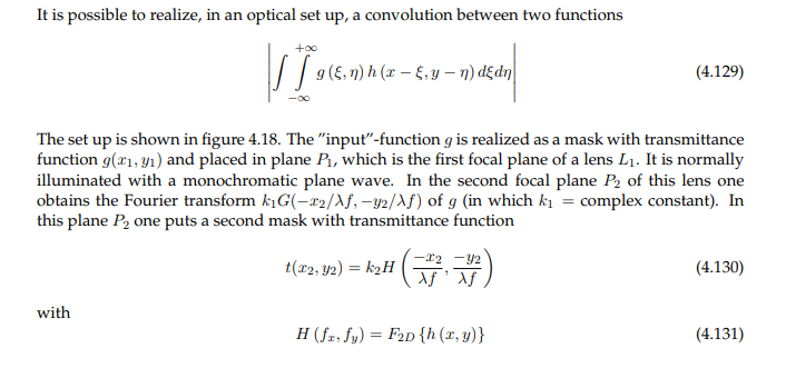
It is possible to realize, in an optical set up, a convolution between two functions $$ \left|\int \int_{-\infty}^{+\infty}g (ξ, η) h (x − ξ, y − η) dξdη\right| \tag{4.129} $$ The set up is shown in figure 4.18. The "input"-function $g$ is realized as a mask with transmittance function $g(x_1, y_1)$ and placed in plane $P_1$, which is the first focal plane of a lens $L_1$. It is normally illuminated with a monochromatic plane wave. In the second focal plane $P_2$ of this lens one obtains the Fourier transform $k_1 G(−x_2/λf, −y_2/λf)$ of $g$ (in which $k_1 =$ complex constant). In this plane $P_2$ one puts a second mask with transmittance function $$ t(x_2, y_2) = k_2 H\left(\frac{-x_2}{\lambda f},\frac{-y_2}{\lambda f}\right), \tag{4.130} $$ with $$ H (fx, fy) = F_{2D} \left\{h (x, y)\right\} \tag{4.131} $$ Behind this mask, the field is proportional to $G.H$ ; hence in the focal plane $P_3$ of the second lens $L_2$ one finds the following irradiance: $$ I (x_3, y_3) = K \left|\int \int_{-\infty}^{+\infty}g (ξ, η) h (x_3 − ξ, y_3 − η) dξdη\right|^2 \tag{4.132} $$ This kind of convolution processor can be practically realized by inserting in the planes $P_1$ and $P_2$ a LC-SLM (Liquid Crystal Spatial Light Modulator). This is a two-dimensional transmission screen, with which one can realize an arbitrary two-dimensional function with the help of a computer. In plane $P_3$ one puts a CCD (Charged Coupled Device) Camera which transforms the optical information in an electrical one. An advantage of this processor is the fact that the "calculations" are done immediately (the speed is only limited by the input and output speed of the LC-SLM and CCD). Disadvantage (as compared to the calculations with a digital computer) is the analog character of the calculations, with its inaccuracy, the non-linearity in the LC-SLM and CCD, and also the aberrations in the lenses. Moreover there is also a technological problem: the function H is usually a complex function. This implies that in plane $P_2$ one needs an SLM in which not only the amplitude, but also the phase transmittance should be simulated electronically; and this is a very difficult technological problem

But I do not agree with its conclusion (I think it is wrong). Indeed, we have (I use a slightly different notation, hope it's clear): $$U(x,y,2f)=kost \ F[g(x_{1};y_{1})]_{(\frac{kx}{f};\frac{ky}{f})}$$ and after the second mask: $$U(x,y,2f)=kost \ F[g(x_{1};y_{1})]_{(\frac{kx}{f};\frac{ky}{f})} F[h(x_{1};y_{1})]_{(\frac{kx}{f};\frac{ky}{f})}$$ Finally: $$U(x,y,4f)=kost \ F(F[g(x_{1};y_{1})]F[h(x_{1};y_{1})])_{(\frac{kx}{f};\frac{ky}{f})}$$ And so I can't say that $U(x,y,4f)$ is the convolution product of $g$ and $h$ because to say it, it should be: $$U(x,y,4f)=kost \ F^{-1}(F[g(x_{1};y_{1})]F[h(x_{1};y_{1})])_{(\frac{kx}{f};\frac{ky}{f})}$$ not?

I was reading Chapter 4, on Fourier Optics, of the course notes on Photonics by Roel Baets and Günther Roelkens (Ghent University, 2009).

I am struggling with the following section:

enter image description here

4.3.5 Optical convolution processor

It is possible to realize, in an optical set up, a convolution between two functions $$ \left|\int \int_{-\infty}^{+\infty}g (ξ, η) h (x − ξ, y − η) dξdη\right| \tag{4.129} $$ The set up is shown in figure 4.18. The "input"-function $g$ is realized as a mask with transmittance function $g(x_1, y_1)$ and placed in plane $P_1$, which is the first focal plane of a lens $L_1$. It is normally illuminated with a monochromatic plane wave. In the second focal plane $P_2$ of this lens one obtains the Fourier transform $k_1 G(−x_2/λf, −y_2/λf)$ of $g$ (in which $k_1 =$ complex constant). In this plane $P_2$ one puts a second mask with transmittance function $$ t(x_2, y_2) = k_2 H\left(\frac{-x_2}{\lambda f},\frac{-y_2}{\lambda f}\right), \tag{4.130} $$ with $$ H (fx, fy) = F_{2D} \left\{h (x, y)\right\} \tag{4.131} $$ Behind this mask, the field is proportional to $G.H$ ; hence in the focal plane $P_3$ of the second lens $L_2$ one finds the following irradiance: $$ I (x_3, y_3) = K \left|\int \int_{-\infty}^{+\infty}g (ξ, η) h (x_3 − ξ, y_3 − η) dξdη\right|^2 \tag{4.132} $$ This kind of convolution processor can be practically realized by inserting in the planes $P_1$ and $P_2$ a LC-SLM (Liquid Crystal Spatial Light Modulator). This is a two-dimensional transmission screen, with which one can realize an arbitrary two-dimensional function with the help of a computer. In plane $P_3$ one puts a CCD (Charged Coupled Device) Camera which transforms the optical information in an electrical one. An advantage of this processor is the fact that the "calculations" are done immediately (the speed is only limited by the input and output speed of the LC-SLM and CCD). Disadvantage (as compared to the calculations with a digital computer) is the analog character of the calculations, with its inaccuracy, the non-linearity in the LC-SLM and CCD, and also the aberrations in the lenses. Moreover there is also a technological problem: the function H is usually a complex function. This implies that in plane $P_2$ one needs an SLM in which not only the amplitude, but also the phase transmittance should be simulated electronically; and this is a very difficult technological problem

But I do not agree with its conclusion (I think it is wrong). Indeed, we have (I use a slightly different notation, hope it's clear): $$U(x,y,2f)=const \ F[g(x_{1};y_{1})]_{(\frac{kx}{f};\frac{ky}{f})}$$ and after the second mask: $$U(x,y,2f)=const \ F[g(x_{1};y_{1})]_{(\frac{kx}{f};\frac{ky}{f})} F[h(x_{1};y_{1})]_{(\frac{kx}{f};\frac{ky}{f})}$$ Finally: $$U(x,y,4f)=const \ F(F[g(x_{1};y_{1})]F[h(x_{1};y_{1})])_{(\frac{kx}{f};\frac{ky}{f})}$$ And so I can't say that $U(x,y,4f)$ is the convolution product of $g$ and $h$ because to say it, it should be: $$U(x,y,4f)=const \ F^{-1}(F[g(x_{1};y_{1})]F[h(x_{1};y_{1})])_{(\frac{kx}{f};\frac{ky}{f})}$$ not?
added 2370 characters in body
Source Link
Emilio Pisanty
  • 135.4k
  • 33
  • 358
  • 677

I was reading this paper: enter image description hereChapter 4, on Fourier Optics, of the course notes on Photonics by Roel Baets and Günther Roelkens (Ghent University, 2009).

enter image description here I am struggling with the following section:

enter image description here

enter image description here

4.3.5 Optical convolution processor

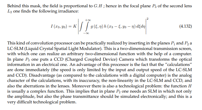
It is possible to realize, in an optical set up, a convolution between two functions $$ \left|\int \int_{-\infty}^{+\infty}g (ξ, η) h (x − ξ, y − η) dξdη\right| \tag{4.129} $$ The set up is shown in figure 4.18. The "input"-function $g$ is realized as a mask with transmittance function $g(x_1, y_1)$ and placed in plane $P_1$, which is the first focal plane of a lens $L_1$. It is normally illuminated with a monochromatic plane wave. In the second focal plane $P_2$ of this lens one obtains the Fourier transform $k_1 G(−x_2/λf, −y_2/λf)$ of $g$ (in which $k_1 =$ complex constant). In this plane $P_2$ one puts a second mask with transmittance function $$ t(x_2, y_2) = k_2 H\left(\frac{-x_2}{\lambda f},\frac{-y_2}{\lambda f}\right), \tag{4.130} $$ with $$ H (fx, fy) = F_{2D} \left\{h (x, y)\right\} \tag{4.131} $$ Behind this mask, the field is proportional to $G.H$ ; hence in the focal plane $P_3$ of the second lens $L_2$ one finds the following irradiance: $$ I (x_3, y_3) = K \left|\int \int_{-\infty}^{+\infty}g (ξ, η) h (x_3 − ξ, y_3 − η) dξdη\right|^2 \tag{4.132} $$ This kind of convolution processor can be practically realized by inserting in the planes $P_1$ and $P_2$ a LC-SLM (Liquid Crystal Spatial Light Modulator). This is a two-dimensional transmission screen, with which one can realize an arbitrary two-dimensional function with the help of a computer. In plane $P_3$ one puts a CCD (Charged Coupled Device) Camera which transforms the optical information in an electrical one. An advantage of this processor is the fact that the "calculations" are done immediately (the speed is only limited by the input and output speed of the LC-SLM and CCD). Disadvantage (as compared to the calculations with a digital computer) is the analog character of the calculations, with its inaccuracy, the non-linearity in the LC-SLM and CCD, and also the aberrations in the lenses. Moreover there is also a technological problem: the function H is usually a complex function. This implies that in plane $P_2$ one needs an SLM in which not only the amplitude, but also the phase transmittance should be simulated electronically; and this is a very difficult technological problem

But I'mI do not agree with its conclusion (I think it is wrong). Indeed, we have (I use a slightly different notation, hope it's clear): $$U(x,y,2f)=kost \ F[g(x_{1};y_{1})]_{(\frac{kx}{f};\frac{ky}{f})}$$ and after the second mask: $$U(x,y,2f)=kost \ F[g(x_{1};y_{1})]_{(\frac{kx}{f};\frac{ky}{f})} F[h(x_{1};y_{1})]_{(\frac{kx}{f};\frac{ky}{f})}$$ Finally: $$U(x,y,4f)=kost \ F(F[g(x_{1};y_{1})]F[h(x_{1};y_{1})])_{(\frac{kx}{f};\frac{ky}{f})}$$ And so I can't say that $U(x,y,4f)$ is the convolution product of $g$ and $h$ because to say it, it should be: $$U(x,y,4f)=kost \ F^{-1}(F[g(x_{1};y_{1})]F[h(x_{1};y_{1})])_{(\frac{kx}{f};\frac{ky}{f})}$$ not?
I was reading this paper: enter image description here

enter image description here

enter image description here

But I'm not agree with its conclusion (I think it is wrong). Indeed, we have (I use a slightly different notation, hope it's clear): $$U(x,y,2f)=kost \ F[g(x_{1};y_{1})]_{(\frac{kx}{f};\frac{ky}{f})}$$ and after the second mask: $$U(x,y,2f)=kost \ F[g(x_{1};y_{1})]_{(\frac{kx}{f};\frac{ky}{f})} F[h(x_{1};y_{1})]_{(\frac{kx}{f};\frac{ky}{f})}$$ Finally: $$U(x,y,4f)=kost \ F(F[g(x_{1};y_{1})]F[h(x_{1};y_{1})])_{(\frac{kx}{f};\frac{ky}{f})}$$ And so I can't say that $U(x,y,4f)$ is the convolution product of $g$ and $h$ because to say it, it should be: $$U(x,y,4f)=kost \ F^{-1}(F[g(x_{1};y_{1})]F[h(x_{1};y_{1})])_{(\frac{kx}{f};\frac{ky}{f})}$$ not?

I was reading Chapter 4, on Fourier Optics, of the course notes on Photonics by Roel Baets and Günther Roelkens (Ghent University, 2009).

I am struggling with the following section:

enter image description here

4.3.5 Optical convolution processor

It is possible to realize, in an optical set up, a convolution between two functions $$ \left|\int \int_{-\infty}^{+\infty}g (ξ, η) h (x − ξ, y − η) dξdη\right| \tag{4.129} $$ The set up is shown in figure 4.18. The "input"-function $g$ is realized as a mask with transmittance function $g(x_1, y_1)$ and placed in plane $P_1$, which is the first focal plane of a lens $L_1$. It is normally illuminated with a monochromatic plane wave. In the second focal plane $P_2$ of this lens one obtains the Fourier transform $k_1 G(−x_2/λf, −y_2/λf)$ of $g$ (in which $k_1 =$ complex constant). In this plane $P_2$ one puts a second mask with transmittance function $$ t(x_2, y_2) = k_2 H\left(\frac{-x_2}{\lambda f},\frac{-y_2}{\lambda f}\right), \tag{4.130} $$ with $$ H (fx, fy) = F_{2D} \left\{h (x, y)\right\} \tag{4.131} $$ Behind this mask, the field is proportional to $G.H$ ; hence in the focal plane $P_3$ of the second lens $L_2$ one finds the following irradiance: $$ I (x_3, y_3) = K \left|\int \int_{-\infty}^{+\infty}g (ξ, η) h (x_3 − ξ, y_3 − η) dξdη\right|^2 \tag{4.132} $$ This kind of convolution processor can be practically realized by inserting in the planes $P_1$ and $P_2$ a LC-SLM (Liquid Crystal Spatial Light Modulator). This is a two-dimensional transmission screen, with which one can realize an arbitrary two-dimensional function with the help of a computer. In plane $P_3$ one puts a CCD (Charged Coupled Device) Camera which transforms the optical information in an electrical one. An advantage of this processor is the fact that the "calculations" are done immediately (the speed is only limited by the input and output speed of the LC-SLM and CCD). Disadvantage (as compared to the calculations with a digital computer) is the analog character of the calculations, with its inaccuracy, the non-linearity in the LC-SLM and CCD, and also the aberrations in the lenses. Moreover there is also a technological problem: the function H is usually a complex function. This implies that in plane $P_2$ one needs an SLM in which not only the amplitude, but also the phase transmittance should be simulated electronically; and this is a very difficult technological problem

But I do not agree with its conclusion (I think it is wrong). Indeed, we have (I use a slightly different notation, hope it's clear): $$U(x,y,2f)=kost \ F[g(x_{1};y_{1})]_{(\frac{kx}{f};\frac{ky}{f})}$$ and after the second mask: $$U(x,y,2f)=kost \ F[g(x_{1};y_{1})]_{(\frac{kx}{f};\frac{ky}{f})} F[h(x_{1};y_{1})]_{(\frac{kx}{f};\frac{ky}{f})}$$ Finally: $$U(x,y,4f)=kost \ F(F[g(x_{1};y_{1})]F[h(x_{1};y_{1})])_{(\frac{kx}{f};\frac{ky}{f})}$$ And so I can't say that $U(x,y,4f)$ is the convolution product of $g$ and $h$ because to say it, it should be: $$U(x,y,4f)=kost \ F^{-1}(F[g(x_{1};y_{1})]F[h(x_{1};y_{1})])_{(\frac{kx}{f};\frac{ky}{f})}$$ not?

Bumped by Community user
Source Link
Landau
  • 768
  • 10
  • 21

Optical convolution processor

I was reading this paper: enter image description here

enter image description here

enter image description here

But I'm not agree with its conclusion (I think it is wrong). Indeed, we have (I use a slightly different notation, hope it's clear): $$U(x,y,2f)=kost \ F[g(x_{1};y_{1})]_{(\frac{kx}{f};\frac{ky}{f})}$$ and after the second mask: $$U(x,y,2f)=kost \ F[g(x_{1};y_{1})]_{(\frac{kx}{f};\frac{ky}{f})} F[h(x_{1};y_{1})]_{(\frac{kx}{f};\frac{ky}{f})}$$ Finally: $$U(x,y,4f)=kost \ F(F[g(x_{1};y_{1})]F[h(x_{1};y_{1})])_{(\frac{kx}{f};\frac{ky}{f})}$$ And so I can't say that $U(x,y,4f)$ is the convolution product of $g$ and $h$ because to say it, it should be: $$U(x,y,4f)=kost \ F^{-1}(F[g(x_{1};y_{1})]F[h(x_{1};y_{1})])_{(\frac{kx}{f};\frac{ky}{f})}$$ not?