Background
As has been stated in the answer you linked to, the propagation of light from the pupil of an imaging system to the image plane can be modeled by a very close approximation called Fraunhofer Diffraction.
$$ U(x,y) \propto \int\int u(\xi, \eta) e^{-i\frac{2\pi}{\lambda z}(x\xi+y\eta)} d\xi d\eta $$
where $\xi$ and $\eta$ are the x- and y- coordinates in the pupil plane, $u(\xi, \eta)$ is the optical field in the pupil plane, and $U$ is the optical field in the image plane.
Under the substitutions
$$ \begin{eqnarray}
\mathcal{f}_x &= &\frac{x}{\lambda z} \\
\mathcal{f}_y &= &\frac{y}{\lambda z} \\
\end{eqnarray} $$
Fraunhoffer diffraction is simply a Fourier transform (FT). Thus it is easier to write:
$$ U(x,y) \propto \mathcal{F}\left[ u(\xi,\eta) \right] $$
where $\mathcal{F}$ will represent the FT, including the necessary scale factors and substitutions mentioned.
A property of the FT important for this discussion is called Convolution Theorem. In terms relevant to this answer, this theorem states that the multiplication of two patterns in the pupil of the lens is equivalent to the convolution of the FT of those patterns in the image plane. We can write this as:
$$ \mathcal{F}\left[ u(\xi,\eta) \right] \otimes \mathcal{F}\left[ p(\xi,\eta) \right] \propto \mathcal{F}\left[ u(\xi,\eta) \times p(\xi,\eta) \right] $$
or
$$ U(x, y) \otimes P(x,y) \propto \mathcal{F}\left[ u(\xi,\eta) \times p(\xi,\eta) \right]$$
where $P(x,y)$ is the FT of the pupil function $p(\xi,\eta)$, and $\otimes$ is the convolution operator.
Answer
So how does this apply in the case of a camera lens? Well, in the pupil of a camera lens, there is some optical field -- i.e. some pattern of light on its way to the image plane. Keep in mind that it is not yet a clearly focused image, but an optical field which will become an image by the time it arrives at the image sensor. Also in this plane is the aperture stop, which blocks some of the light. This aperture stop can be considered as a function which is multiplied by the light field on its way through the pupil. It multiplies the incoming filed by 1 where there aperture is clear, and by 0 where light is blocked. In other words:
$$ p = \left\{
\begin{array}{rl}
1 & \text{where the aperture is clear} \\
0 & \text{where the aperture blocks light}
\end{array} \right. $$
So, based on the background given above, we know that the image we see will be the convolution of the ideal image $U$ with the FT of the pupil function, $P$. This will make bright light sources in the image take on the shape of the FT of the pupil function, which is why $P$ is typically called the point spread function (PSF) of the camera lens*.
So what does $P$ look like? The exact computation of the necessary FT is messy and complicated, but there is a basic rule of thumb which provides a good qualitative description of the FT of some basic shapes:
Sharp edges in the input to the FT are represented by bright streaks in the output, with the orientation of the streak being perpendicular to the edge which produced it.
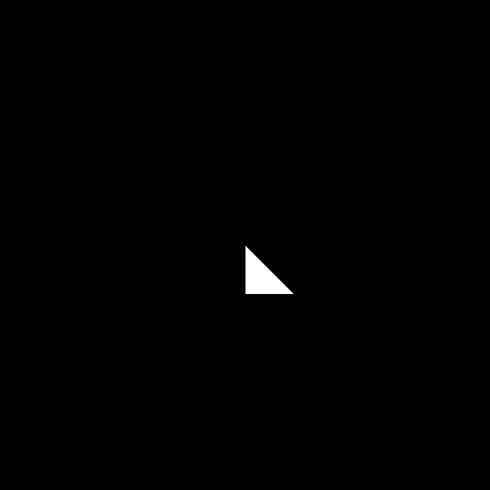
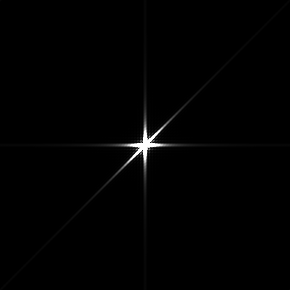
So, a triangular aperture has 3 sharp edges, and therefore the resulting PSF has 3 streaks, which produces a 6-pointed star. In the images below you can see an example in which I have produced a triangular shape to represent the lens aperture, and the resulting PSF:


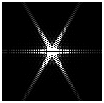
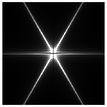
In the (more realistic) case of a hexagonal aperture, there will technically be 6 streaks, but because the opposite sides of a hexagon are parallel to each other, the streaks in the PSF will be in parallel pairs, so they will overlap and you will only see 3 distinct streaks in the image.
*This is only true in the case where the lens is optically perfect. In reality, aberrations in the optics also contribute to the PSF, but a description of that is beyond the scope of this answer.


