-1
$\begingroup$

I'm working on understanding the dynamics of a rigid body, and I've come across a formula that I'm trying to make sense of. The formula is:

enter image description here

Where M is:

enter image description here

and C(w) is

enter image description here

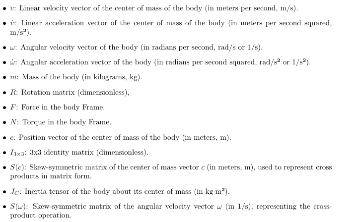
The Parameters used in these formulas above are defined as

enter image description here

What I Think the Formula Represents:

The formula seems to represent the equations of motion for a rigid body under external forces and torques. The left side includes the effects of inertia (mass and moment of inertia) and possibly some Coriolis and centrifugal forces, while the right side represents external forces and torques applied to the body.

My Questions:

  1. Is this formula correct in its current form? Should there be an additional term like enter image description here to properly account for the Coriolis and centrifugal forces? This would make the equation of the dynamics of a rigid body be enter image description here

  2. What is the correct interpretation of each term in this formula? Specifically, how do the matrices M and C(ω) relate to the physical properties of the rigid body (like mass, center of mass, and inertia tensor)?

  3. Is there a more standard form for expressing the rigid body dynamics equations that includes these terms, and how does this relate to my current understanding?

I would appreciate any insights or explanations, especially if they can clarify whether this formula is accurate or if there is a common version that I'm missing.

Thank you!

$\endgroup$
2
  • $\begingroup$ Coriolis force must have somewhere factor 2 $\endgroup$
    – Eli
    Commented Sep 19 at 13:38
  • $\begingroup$ Those equations describe the equation of motion for rigid body, in a coordinate system that parallel to to the Com system ? $\endgroup$
    – Eli
    Commented Sep 19 at 13:51

2 Answers 2

0
$\begingroup$

$\def \b {\mathbf}$

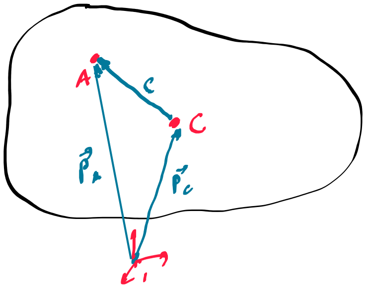
enter image description here The equations of motion at point A

the position vector, velocity and acceleration at point A , given in inertial system \begin{align*} &\b P_A=\b P_C+\b R\,\b c\quad,\text{the velocity}\\ &\b{\dot{P}}_A=\b{\dot{P}}_C+\b{\dot{R}}\,\b c \quad,\text{the acceleration}\\ &\b{\ddot{P}}_A=\b{\ddot{P}}_C+\b{\ddot{R}}\,\b c \end{align*} with \begin{align*} & \b{\dot{R}}=\b R\,\b\omega^\times\quad, \b{\ddot{R}}=\b{\dot{R}}\,\b\omega^\times+\b R\,\b{\dot{\omega}}^\times\\ & \b{\ddot{R}}=\b R\,\b\omega^\times\,\b\omega^\times+\b R\,\b{\dot{\omega}}^\times\\ \end{align*} thus the acceleration \begin{align*} &\b{\ddot{P}}_A=\b{\ddot{P}}_C+\b R\left(\b\omega^\times\,\b\omega^\times+ \,\b{\dot{\omega}}^\times\right)\,\b c\quad,\text{or}\\ &\b R^T\,\b{\ddot{P}}_A=\underbrace{\b R^T\,\b{\ddot{P}}_C}_{\b{\dot{v}}}+ \left(\b\omega^\times\,\b\omega^\times+ \,\b{\dot{\omega}}^\times\right)\,\b c \end{align*}

the EOM's translation \begin{align*} &m\,\b{\ddot{P}}_A=\b F\quad,m\,\b R^T\,\b{\ddot{P}}_A=\b R^T\,\b F\quad\Rightarrow\\ &m\,\b{\dot{v}}+ \left(\b\omega^\times\,\b\omega^\times+ \,\b{\dot{\omega}}^\times\right)\,\b c= \b R^T\,\b F \end{align*} The EOM's rotation \begin{align*} &\b J_A\,\b{\dot{\omega}}+\b\omega^\times\left(\b J_A\,\b\omega\right)=\b\tau\quad,\text{where}\\ &\b J_A=\b J_C+m\,\b c^\times\,\b c^\times \end{align*} Translation and rotation \begin{align*} &\begin{bmatrix} m\,I & -\b c^\times \\ \b 0 & \b J_A \\ \end{bmatrix} \begin{bmatrix} \b{\dot{v}} \\ \b{\dot{\omega}} \\ \end{bmatrix}+\begin{bmatrix} \b\omega^\times\,\b\omega^\times\,\b c \\ \b\omega^\times\left(\b J_A\,\b\omega\right) \\ \end{bmatrix}= \begin{bmatrix} \b R^T\,\b F \\ \b \tau \\ \end{bmatrix}\quad,\text{with}\\ & \b\omega^\times= \left[ \begin {array}{ccc} 0&-\omega_{{3}}&\omega_{{2}} \\ \omega_{{3}}&0&-\omega_{{1}}\\ -\omega_{{2}}&\omega_{{1}}&0\end {array} \right] \quad, \b c^\times= \left[ \begin {array}{ccc} 0&-c_{{3}}&c_{{2}}\\ c_{ {3}}&0&-c_{{1}}\\ -c_{{2}}&c_{{1}}&0\end {array} \right] \end{align*}

  • $~\b R~$ Rotation Matrix from body system to inertial system
  • $~\b F~$ external force , given in inertial system
  • $~\b\tau~$ external torque , given in body system
  • $~\b J_C~$ Inertia tensor an the center of mass
  • $~\b J_A~$ Inertia tensor, at point A , the coordinate system is parallel to the center of mass coordinate system
$\endgroup$
0
$\begingroup$

The context in which I see this notation used most often is for robotic manipulators. Although in that case, the system is made up of a number of rigid bodies with 1 DOF joints. $\bf M$ is called the "mass matrix" and depends ONLY on position variables. It is what multiplies the acceleration terms in the force/torque balance. $\bf C$ (also called $\bf V$) is a vector (not matrix) of coriolis and centrifugal forces. In robotics, they also include a (vector) $\bf G$ term to account for gravity effects and a $\bf \tau$ vector of applied forces and torques. A practical engineering approach with clear explanation (i.e. no fancy math jargon) can be found in "Introduction to Robotics" by John Craig.

$\endgroup$
1
  • 1
    $\begingroup$ Thank you so much, this is indeed for a robots application. And latter in the system i do include the G term, but my main problem is with the C matrix. I will read the book and hopefully i can understand better what i am working with. $\endgroup$ Commented Sep 20 at 10:57

Your Answer

By clicking “Post Your Answer”, you agree to our terms of service and acknowledge you have read our privacy policy.

Not the answer you're looking for? Browse other questions tagged or ask your own question.