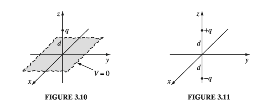
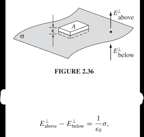
Consider the figure 3.10. How do we apply the electrostatic boundary conditions here in order to get the expression for induced surface charge density. Comparing with figure 2.36, what would be E(above) and E(below) in this case? What would be the direction of the outward normal (ncap)? Please explain.
2 Answers
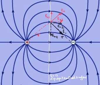
The plane at zero potential is an equipotential in a two, equal magnitude, opposite charge, system.
At any position on that plane there is an electric field due to the positive charge $\vec E_+$ and an equal magnitude electric field due to the negative charge $\vec E_-$ as shown on the diagram.
Resolving the two field one notes that parallel to the plane the components of the fields, $E_{+\parallel}$ and $E_{-\parallel}$, cancel and that leaves the two perpendicular components, $E_{+\perp}$ and $E_{-\perp}$, which you were asking about although I have not drawn them above and below the plane.
The magnitudes of fields $\vec E_+$ and $\vec E_-$ are equal to the electric field from a point charge at a distance $r$ from the charge.
Suppose that the potential Function is given by $V(x,y,z)$ then the boundary conditions would be
- $\lim_{x \rightarrow \pm \infty} V(x,y,z) = 0$ and the same will be true for $y$ and $z$ going to infinities
- $V(x,y,z) = 0, z \leq 0$
regarding the Electric fields you will have the following
$E(x,y,\mu) = 0\hat{i} + 0\hat{j} + \frac{2qd}{4\pi\epsilon_0(x^2 + y^2 + d^2) }\hat{k} $ upto first order as $\mu$ goes to $0+$
and below that plane $E$ is $0$ vector


