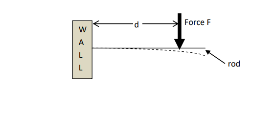
This is treated by Euler-Bernoulli beam theory. For a cantilever beam of length $L$ with end load $F$, as you have requested, the displacement $w$ as a function of distance $x$ from the suspension point is
$$w(x)=\frac{Fx^2(3L-x)}{6EI}$$
where $E$ is Young's modulus.
Note that the pieces of information you have listed are not sufficient. You also need the area moment of inertia
$$I=\int \int \chi(y,z) z^2 dy dz$$
which is determined by the cross-sectional shape of the beam with respect to the loading direction. It is a measure of the bending stiffness of the rod irrespective of length and elastic modulus. Generally a hollow profile of the same mass or area as a filled profile is stiffer (greater I). Also, a taller (in relation to the loading direction) profile is stiffer than a flatter profile at the same mass or area.
The characteristic function $\chi(y,z)$ above assumes the value $1$ inside the solid material of the beam, while it is zero outside the beam (which makes the outside not contribute to the stiffness of the beam, which is pretty reasonable). You can find the $I$ of many common beam sections tabulated, so that it is often not necessary to do the integration yourself.
Note also, that the end displacement (where the force acts, $x=L$) is
$$y=w(L)=\frac{FL^3}{3EI} \qquad \Longleftrightarrow \qquad F=\frac{3EI}{L^3}y$$
which makes
$$k=\frac{3EI}{L^3}$$
Hooke's stiffness of the beam as a whole. Since Hooke's law is a linear relationship of $y$, it is clear that Euler-Bernoulli theory is just an approximation which is accurate enough only for smaller displacements, long before geometric nonlinearities kick in.
Finally, if, as indicated in your drawing, the force is not applied at the end of the beam, the length $L$ has still to be taken as the coordinate where the forces acts. The remaining arm length (beyond the force action point) will just stay approximately straight and you can calculate its displacement purely geometrically from $w(x)$ and its derivative.

