2
$\begingroup$

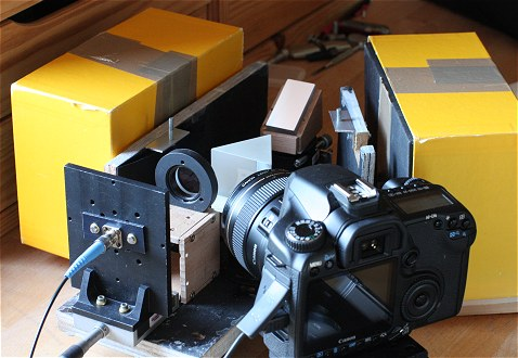
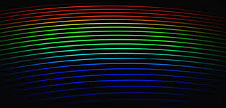
I am trying to make an educational echelle spectrograph using easily available materials, basically in a cardboard box. An echelle grating (36 lines/mm) needs another prism to do a cross dispersion and generate a two dimensional spectrum like the following (taken from a astro website).

enter image description here

The design I have is a very "crude" version of the following taken from Astro website. The key difference is that I want to use a slit and a fluorescent lamp as a light source instead of a fiber and the camera is an ordinary digital camera rather than a fancy DSLR. http://www.astrosurf.com/buil/echelle/first.htm

enter image description here

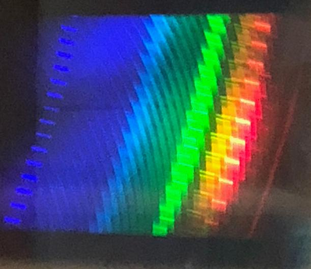
One can readily generate this type of spectrum using any white LED without any collimation. Simply illuminate the echelle and view it via prism. The problem starts with any other light source such as a fluorescent lamp. The requirement to generate a successful echellogram is to have collimated light.

Questions:

  1. What is special about LED that it does not need collimation? Even a cell phone light produces a beautiful echellogram, exactly as pictured above.

  2. As stated above, problem is with other light sources such as a fluorescent lamp or street light. Does anyone know of a good trick for decent collimation of light from slits made in a cardboard box? Light spreads out a lot from the slit as a wide cone of light.

If we make a simple slit with the help of blades on a cardboard (approximately 0.5 mm wide, 0.8 cm long) and if we place a fluorescent lamp very close to the slit and a lens with its focus at the slit, collimation is poor. The lens is a 25mm Dia. x 100mm Focal length, Achromatic Doublet Lens. By poor collimation, I mean that the echellogram shows repeating images which is a sign that the light is not well collimated.

enter image description here

$\endgroup$

1 Answer 1

2
$\begingroup$

There are two issues here I think warrant comment.

First, the collimation of an extended source by a mirror or lens is limited by the lateral extent of the source and the focal length of the collimating lens or mirror. If you consider the path of a ray from the edge of the slit through the center of the lens, the angle with respect to the optical axis is given by ArcTan[w/(2 f)], where w is the full width of the slit. For a 0.5mm slit and a 100mm focal length lens this is 0.14 degrees. So the collimated beam will have a half-angle angular extent of 0.14 degrees. For a 500mm focal length, that is reduced to 0.029 degrees. I don't know if that is a sufficient improvement. To really quantify this would best be done with a simulation in an optical design tool such as Zemax OpticStudio.

The second comment concerns where unwanted light goes. Spectrometers are etendue limited devices and in your case is appears you are designing for F/4 . ( 100m / 25mm). This is typical in that slower systems capture less light and faster systems have more aberrations. Good designs generally manage stray light by internal baffles but also by limiting the light cone into the system to that which progresses through the system as intended. By placing the fluorescent lamp directly against the slit you are allowing a much wider cone of light than the spectrometer will accept. You are relying on the mount around the collimating lens to block the excess light. Another way to do this would be to focus the light from this first slit onto a second slit with a lens and housing that permits only F/4 light to reach the second slit.

Kind regards, David

$\endgroup$
5
  • $\begingroup$ Thanks for comments. I was currently trying the last suggestion. The idea is to place the light source (ordinary fluorescent lamp) 10 focal lengths away from 3 mm id lens. The lens has a focal length of 50 mm. This lens focuses an image of the light source on the slit. On the other side of the lens I have a 2.5 cm 100 mm focal length lens for collimation. On a piece of paper I can see a nice round beam, there are still multiple repeating images after cross dispersion, which indicates collimation is not perfect as yet. $\endgroup$
    – ACR
    Commented Sep 20, 2020 at 22:46
  • $\begingroup$ Do you know a very simple experimental test for collimation, which confirms that beam is perfectly collimated or not. $\endgroup$
    – ACR
    Commented Sep 20, 2020 at 22:46
  • 1
    $\begingroup$ In focusing the source onto the slit what is really required is that the cone of light focused on the slit matches the f number of the spectroscope. One way to measure the collimation of a beam is to put it through a lens and inspect the spot formed at the image plane. For a diffuse source this would be the location where the smallest spot occurs. $\endgroup$ Commented Sep 20, 2020 at 23:08
  • $\begingroup$ Note that perfect collimation of an extended source is not possible. $\endgroup$ Commented Sep 20, 2020 at 23:13
  • $\begingroup$ Okay thanks. I can easily make an echellogram with even a cellphone's LED (without using any collimator). Focus test is a good idea. Will that. I was using a solution of highlighter ink to see the shape of fluorescent beam in water. $\endgroup$
    – ACR
    Commented Sep 20, 2020 at 23:33

Your Answer

By clicking “Post Your Answer”, you agree to our terms of service and acknowledge you have read our privacy policy.

Not the answer you're looking for? Browse other questions tagged or ask your own question.