1
$\begingroup$

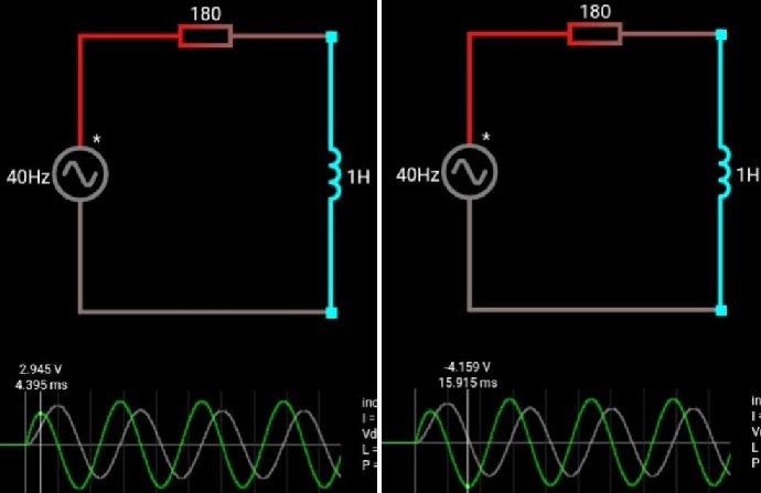
This is the simulation of a RL circuit with an AC source.

That AC source is connected with the circuit at the moment when the source voltage has zero phase angle with 5 volts peak.

It can be seen from the simulation that the peak voltage of the first half cycle (which is the transient I know) is less than the peak voltage of the negative half cycle and rest of the cycles.

I want to know whether that the peak voltage of the positive half cycle is less than the peak voltage of the rest of the cycles is because of any simulation error or is there any other reason?

Plus

When the value of the resistor is increased the transient current and voltage die off more quickly.

Please anyone tell me that why increasing resistance makes the transient to die off quicker?

Infact why resistance make the transients to die off?

I need detail answers of these question. So please if anybody can help!

enter image description here

$\endgroup$
2
  • 1
    $\begingroup$ Forget the simulation. Do you know how to calculate the currents and voltages for a series RL circuit connected to an ac source? $\endgroup$
    – Bob D
    Commented May 2, 2020 at 8:51
  • $\begingroup$ i have solved differential equation realted to the transient circuits. i was just trying to have intuition and to understand circuit logically. $\endgroup$
    – Alex
    Commented May 2, 2020 at 11:08

1 Answer 1

1
$\begingroup$

First, the simulation tells the truth. The transient behavior at the beginning is not an error.

As @BobD already suggested, do not begin with looking at the simulation result. Instead, you should choose the mathematical way to get an understanding where this result comes from.

I assume you already know, that the voltage across a resistor $R$ is $V_R(t)=RI(t)$ and the voltage across an inductor $L$ is $V_L(t)=L\frac{dI(t)}{dt}$. So for your electric circuit you have the differential equation for the current $I(t)$ $$V_\text{peak}\sin(\omega t)=RI(t)+L\frac{dI(t)}{dt}$$ together with the start condition $I(0)=0$.

I will not solve this differential equation for you here. You should work through the math by yourself. Then you will find, the solution $I(t)$ has two components:

  • a transient component proportional to $e^{-Rt/L}$ (i.e. it dies off after $t\gg\frac{L}{R}$),
  • an oscillating component proportional to $\cos(\omega t)$ and $\sin(\omega t)$.

Finally, from the current $I(t)$ you can easily calculate the voltages $V_L(t)$ and $V_R(t)$. You will find, they also have a transient and an oscillating component.

$\endgroup$
1
  • $\begingroup$ thanks alot for your answer. i have solved differential equation realted to the transient circuits. i was just trying to have intuition and to understand circuit logically. $\endgroup$
    – Alex
    Commented May 2, 2020 at 11:06

Your Answer

By clicking “Post Your Answer”, you agree to our terms of service and acknowledge you have read our privacy policy.

Not the answer you're looking for? Browse other questions tagged or ask your own question.