2
$\begingroup$

Sorry, I'm already ashamed to ask for your help. But I'm feel that I needed in some hints about how to imagine alternating current. I really realize I have trouble with it during reading this document (full but old version is here). There is image on p.29:

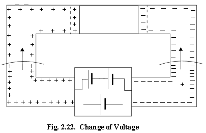
enter image description here

At first, this simple circuit consisting of a battery and a resistor was in some steady state with constant voltage and current all around. Then source voltage is doubled. And there is this transient phase on the image during which a new voltage is forming. Pluses/minuses represent surface charges on the wires. The change in charge distribution travels like a wave-front through the circuit with speed of light.

I explicitly divide all these states apart. Like, 1st steady state with some current in accordance with Ohm's law > transient phase > new steady state after doubled voltage reached resistor with increased current in wires and the resistor.

My problem is that when I try to image AC voltage source instead of DC the mess begins. Since, roughly speaking, there is no steady states now, voltage and charge distribution on the wires is constantly changing. Because of this its hard for me to imagine alternating current in the circuit.

Maybe it would be a little easier for me if I knew the following. On the image above, there are 2 regions, behind "wave front", where a new doubled voltage has already been formed and ahead of it, where voltage is still old.

So my question is about currents in these regions. Is there in the region behind "wave front" already increased current and its value satisfying I = V/R and ahead the front, correspondingly, old value of current ?

If so, I can imagine AC more or less as follows: as voltage propagates down the wires it cause appropriate currents (according to Ohm's law), lets say, in vicinity of wave front. And since length of wires is small in this case, one can think as in some instant of time wave front "ran" through all wire and reach it end. And so we have some concrete equal value of potential for entire length of the wire and appropriate current's value in it.

If this is a wrong idea then I'm lost and would like to hear some tips about how to imagine it. Thanks for the help.

Updated: Now I think this is most likely incorrect because in that case even in an open AC circuit there would be a "normal" current. Well, after a couple of days of reflection and re-reading I realize I'am confuse charge redistribution processes with "main" current so nevermind. I'm going to rephrase the question.

$\endgroup$
5
  • $\begingroup$ What are the pluses/minuses here supposed to represent? In a typical conducting circuit, there is only one type of charge carrier, with only one charge (usually negatively-charged electrons in a metal). In your example above, the electric potential of a DC circuit will be decreasing from a maximum at the positive terminal of the battery, to a minimum at the negative terminal. The charge carriers will all be flowing with a constant bulk speed around the circuit. $\endgroup$
    – Time4Tea
    Commented Jul 29, 2018 at 0:23
  • $\begingroup$ Pluses/minuses represent surface charges on the wires. $\endgroup$
    – Steve T.
    Commented Jul 29, 2018 at 2:45
  • $\begingroup$ Is there any caption under the image in the book, or other text in the book describing what's going on in the image? From the image alone I can't make heads or tails of it. $\endgroup$
    – Bob D
    Commented Jul 29, 2018 at 17:33
  • $\begingroup$ @SteveT. I think those diagrams in your reference are confusing and overly-simplistic. In a conducting circuit, there is only one type of charge carrier (negative electrons), which have a bulk flow velocity around the circuit, in response to an imposed electric field. $\endgroup$
    – Time4Tea
    Commented Jul 30, 2018 at 17:12
  • $\begingroup$ @ Time4Tea Thanks for attempt to help, I confuse myself and going to read more for now. $\endgroup$
    – Steve T.
    Commented Jul 30, 2018 at 17:58

3 Answers 3

1
$\begingroup$

The picture is erroneous. There are no plus charges on the positive end and no minus charges on negative end. The charges in wires of both sides are the same. It's their moving direction that makes difference. For alternative current, the charges (electrons) don't move far away, but viberat at their equilibrium position, e.g. move back and forth at the frequency of the AC.

$\endgroup$
0
$\begingroup$

Think of it as DC, which changes polarity sixty times a second (60cycle alternating current) It's exactly like that in simplest terms possible.

$\endgroup$
1
  • $\begingroup$ Steve T., also realize that the actual drift speed of the electrons in the wires is VERY slow. This means that for alternating current, individual electrons move back and forth (they wiggle) about a fixed position at the frequency of the electric field in the wire (in the U.S., that's 60 cycles/second). $\endgroup$ Commented Jul 30, 2018 at 19:08
0
$\begingroup$

If the top of the picture want to indicate an open circuit, then an AC current will act like if the conductors on the left and right are the plates of a capacitor. On each half cycle, a small current will flow to move electrons toward the negative side, on the right side in the drawing. Half a cycle later, the polarity will be inverted, the left side gaining more electrons.

$\endgroup$

Your Answer

By clicking “Post Your Answer”, you agree to our terms of service and acknowledge you have read our privacy policy.

Not the answer you're looking for? Browse other questions tagged or ask your own question.