2
$\begingroup$

Background to problem

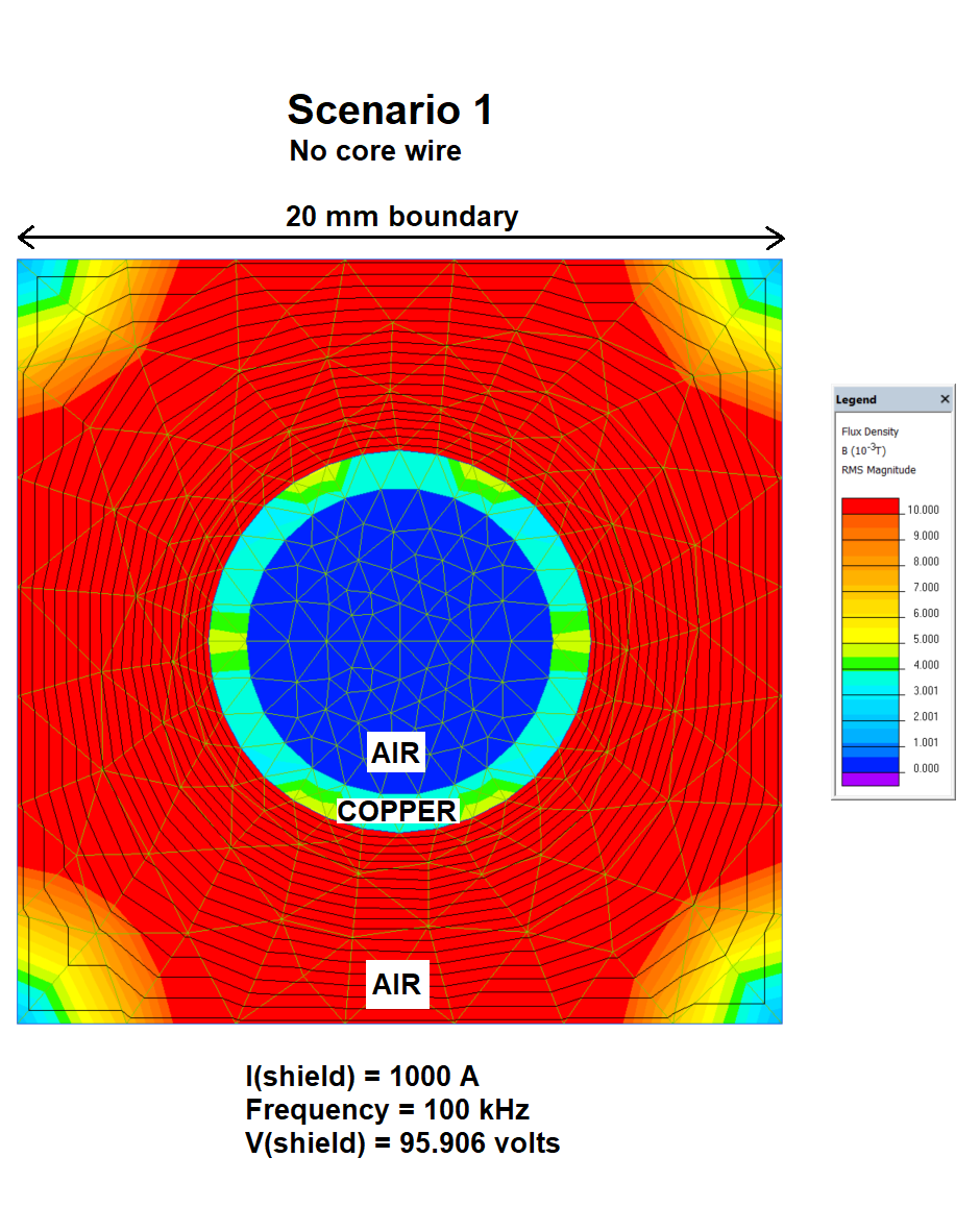
Conventional wisdom informs that the magnetic flux density inside a tube carrying current is zero everywhere. Pictorially this is represented by this finite element analysis (courtesy of QuickField running an AC magnetics problem): -

enter image description here

I have the equivalent of a cable shield/screen at a radius of 4.5 mm and it's 1 mm thick copper. The QF simulation is setup to apply 1,000 amps through the copper shield and a frequency of 100 kHz. QF reports that the resulting shield voltage is 95.906 volts.

Adding a wire core at dead centre

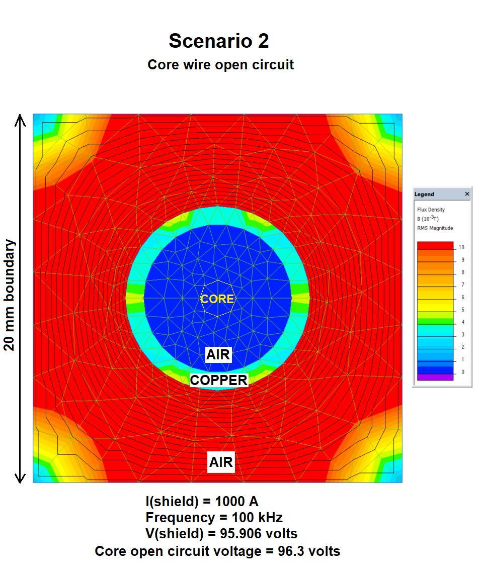
Again, conventional wisdom informs that if the wire/core is open circuit i.e. has no voltage/current source applied, the flux density field pattern should look like the one above (and it does): -

enter image description here

However, there is one small "anomaly" and that is that QF reports that the core voltage is 96.3 volts. Given that there is (or appears to be) no coupling flux between the shield and the inner core, how can the inner core acquire this voltage?

Shorting the inner core (applying a 0 volt source)

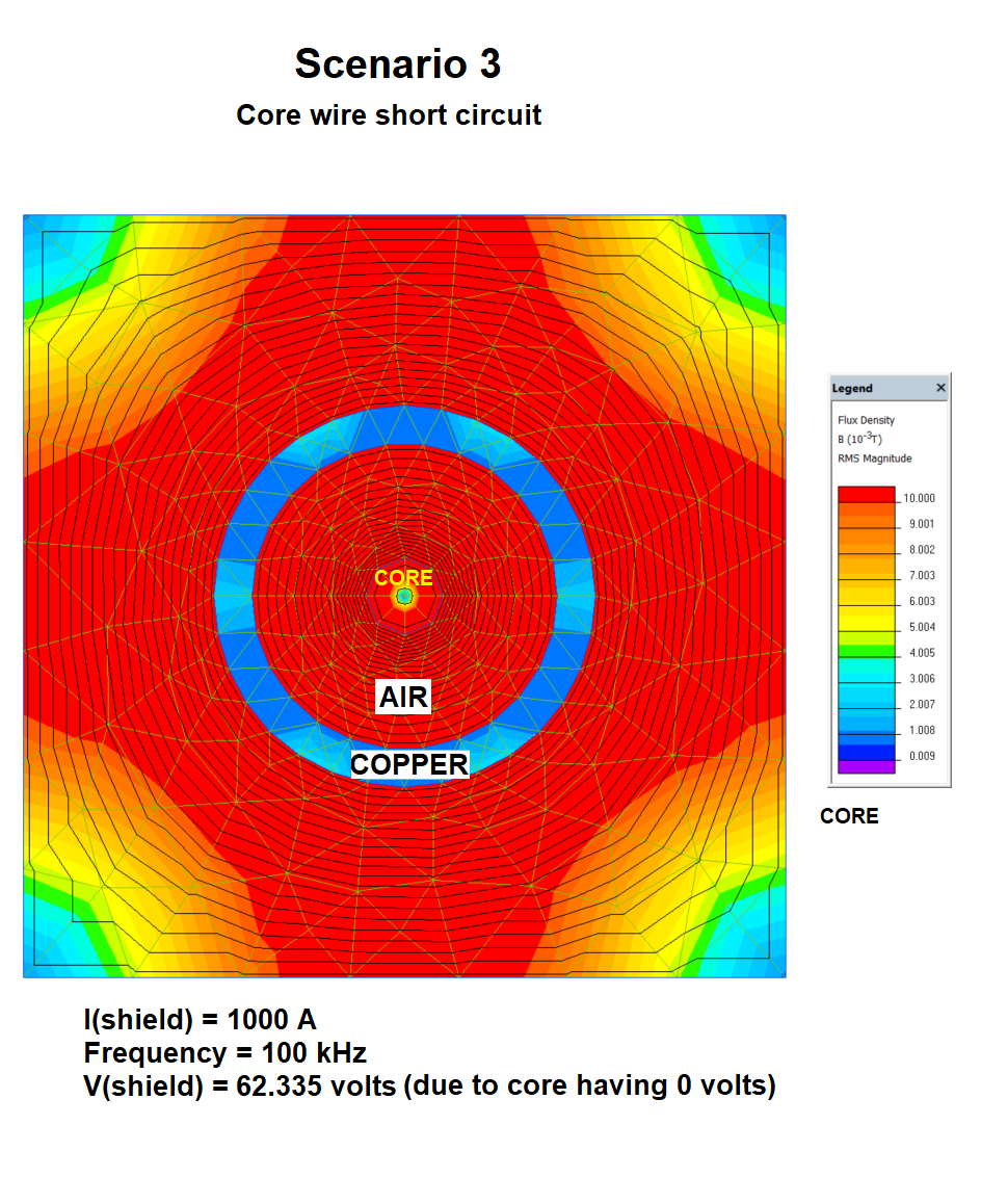
Here's where I'm confused because, with the inner core shorted out, there is now a significant magnetic flux density inside the shield: -

enter image description here

Maybe the clue here is that in scenario 2, the terminal voltage on the core is 96.3 volts and somehow this voltage is acquired due to induction even though the flux density appears to be zero.

I also note that in scenario 3, the shield/tube voltage has dropped from 95.906 volts to 62.335 volts.

My main question

How does an inner conducting core inside a current tube acquire a voltage/potential along its length (scenario 2) in the apparent absence of any coupling flux?

Maybe I'm just not very good at using the simulator?

$\endgroup$

2 Answers 2

0
$\begingroup$

In senario 2 there is no electric field between the core and the shield, so both must be at the same potential.

In scenario 3 it is not clear what you mean by "shorted out." If you mean that the core is grounded, then there is a potential difference between shield and core, so they are acting as a capacitor. Current will therefire run into and out of the core during each cycle. This will produce a magnetic field between the shield and core.

$\endgroup$
2
  • $\begingroup$ The AC magnetics analysis does not "recognize" the effects of capacitance between cores. It's a simple solver that works only on the magnetic fields not the electric fields. I think the likely answer is that irrespective of zero magnetic field lines close to the inner, there are field lines that suround it at distances outside the outer shield hence, induction does take place based on the rate of change of the total flux to infinity. Shorting the inner means applying a 0 volt source across its ends just like I applied a current source across the ends of the outer. $\endgroup$
    – Andy aka
    Commented Jul 15, 2019 at 17:55
  • $\begingroup$ @Andyaka According to Faraday's law, changing magnetic field creates changing electric fields. Since you have AC current and therefore changing magnetic field, wouldn't disregarding electric fields, generally speaking, lead to incorrect results regarding the voltage? $\endgroup$
    – Pygmalion
    Commented Sep 15, 2019 at 9:44
0
$\begingroup$

However, there is one small "anomaly" and that is that QF reports that the core voltage is 96.3 volts.

The lack of magnetic flux between the shield and the inner core is a red herring. Reason:

Voltage induction to the inner core from a current in the shield doesn’t become zero because the field lines inside the shield are zero. There are still field lines outside/beyond the shield and these are just as relevant to induction. Those field lines beyond the shield still surround the inner core.

The lack of field lines immediately surrounding the inner core does not magically “insulate” that inner core from induction.

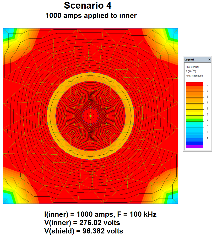
Another argument: imagine the current was fed down the inner core instead of the shield – the field lines would extend out from the inner core (through the shield) to infinity and clearly, this means that the shield is inductively coupled to the inner core. If this is accepted this then it is logical to accept that the reverse transformer process is also true: -

enter image description here

Here we can see that the induced voltage in the shield is almost identical to that in scenario 1 (about 96 volts) and, as such, we would expect the field distribution and density outside the shield in scenario 4 to be identical to that in scenario 1. The same colour-field strength relationship is used and there is barely any visible difference.

The fact that the inner core develops a voltage of 276 volts is due to the increased inductance of that inner core because it is much smaller than the shield i.e. thicker wires have less self inductance.

$\endgroup$

Your Answer

By clicking “Post Your Answer”, you agree to our terms of service and acknowledge you have read our privacy policy.

Not the answer you're looking for? Browse other questions tagged or ask your own question.