1
$\begingroup$

I am designing an electromagnet which will be used to test magnetic sensors. So I used to formula found at hyperphysics which relates the magnetic field flux density to the number of turns, the current and the material permeability.

However after buying a 10cm length of rod of Fe55Ni45 (which has a magnetic permeability of at least 6000) the results are disappointing.

I wound 36 turns around the core and put 200 milli-Amps through the windings. However with my calibrated Gauss meter I can only see that the electromagnet is producing around 5mT. This is much lower than the expected value!

Surely if: N = 36 I = 0.2 k = 6000 L = 0.1

Then B should be 0.54 Tesla

This is below the stated saturation value of the material (1.6 Tesla).

I am starting to think that the problem is the shape of the electromagnet. It is a rod wound with wire. I am measuring the magnetic flux density at the end of the rod. Is the formula I have used for flux density at the centre of the core? If so perhaps there are some suggestions of how to generate a high but accessible magnetic flux density using the equipment I have. Does anyone have experience of such systems?

Thanks for any answers...

enter image description here

$\endgroup$
1
  • $\begingroup$ Please use MathJax to write formulas or formula-like objects. It really improves your question. $\endgroup$ Commented Oct 26, 2015 at 9:36

2 Answers 2

1
$\begingroup$

I will let someone else walk you trough the math of the problem and will give a few experimental pointers on what the solution looks like.

If you want to generate strong fields with an electromagnet, then you need a closed magnetic path which is only disrupted in the volume where you want to access the field. This is what a typical laboratory electromagnet design looks like: http://appliedmagnetics.com/electromagnets.html . The closed magnetic path can not be "replaced" by using a (basically unsuitable) magnetic material with large permeability. OTOH, if you don't care much about the quality of the field and it doesn't have to be variable, I would strongly recommend to use permanent magnets.

The easiest way to build an electromagnet that actually works is probably by taking one or two large power transformers with E-core (they look like this http://k5rmg.com/old-web/Pages/Tech%20Articles/Article%20Images/Jan,%20E-I_core.gif) apart and to use the existing low voltage windings for excitation. Get yourself a transformer where the laminate isn't welded together, otherwise you are in for some nasty machining. The air gap can be easily created by putting a few laminate sheets into the outer legs of the E-core, leaving the gap in the center for your experiment volume.

You will also need a power supply that can handle the inductive load, a lead acid battery is probably best (as you will need several A of current). Electronic supplies will likely die the first time you turn the current off because these transformers do store quite a bit of energy when current is flowing trough them, all of which will be dumped right back into the power supply as a nasty inductive high voltage spike when the supply is being turned off. At the very least you will need protection diodes that can take care of a few hundred Ampere peak current while absorbing the energy.

$\endgroup$
5
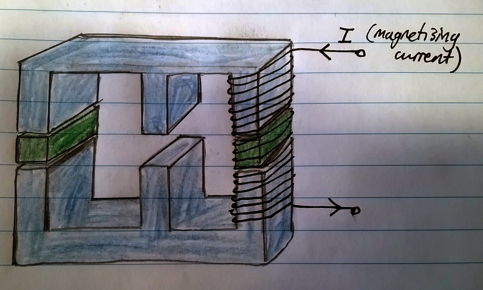
  • $\begingroup$ Thanks, I have added a picture of what I will make now using your suggestion. I have sourced an E core with a suitable cross sectional area (uk.farnell.com/epcos/b66371g0000x187/ferrite-core-e-71-n87/dp/…). Is this what you meant by your description? Should he "green" material in my diagram be made from the same material as the core or is it's selection not important? $\endgroup$
    – ab138
    Commented Oct 27, 2015 at 10:04
  • $\begingroup$ I would suggest to put the coil on the center of the core because you want to magnetize as much of the material as you can. If you put the winding on just one of the outer legs, then you will only achieve a fraction of the possible magnetization in the center. The core you want to use has a rather low saturation field (320mT), so you won't be happy with that, either. This may be counterintuitive, but 100 year old transformer steel is actually better than modern ferrite materials for your application. Ferrite works better for high frequency transformers, but it's not as good in DC applications. $\endgroup$
    – CuriousOne
    Commented Oct 27, 2015 at 10:17
  • $\begingroup$ May I ask what you are trying to do with this electromagnet? $\endgroup$
    – CuriousOne
    Commented Oct 27, 2015 at 10:23
  • $\begingroup$ It is for characterising a magnetic sensor. I understand about the steel but this may be hard to find online. That is why I went for the rod initially because of the high saturation flux density but it is hard to find those materials with the right shapes. However 320mT should be OK to begin with for proof of concept. Which material should I use to buffer the two cores so in order to create a gap? $\endgroup$
    – ab138
    Commented Oct 27, 2015 at 10:29
  • 1
    $\begingroup$ Like I said, buy an entire transformer (or get an old one out of an old appliance!) and take it apart. I have done this dozens of times as a teenager and as a professional to solve similar problems. I am not quite sure how you imagine to be able to characterize a magnetic sensor with this... the non-linearities of the magnetization curves of these materials are far worse than the properties of your sensor. You will be measuring one unknown with another one. If you need a well defined magnetic field then you need to use an air-coil and live with the required large currents. $\endgroup$
    – CuriousOne
    Commented Oct 27, 2015 at 19:00
1
$\begingroup$

The formula on hyper-physics is indeed an approximation for near the center of a long solenoid. It's going to be significantly less (although a factor of 100 sounds a bit extreme...) near the edges, and if your piece of iron isn't thin the "long" solenoid approximation isn't going to be any good either. Also, if the solenoid is small then your tesla-meter might be averaging over some small area (where the peak would be closest to the center of the axis and closest to the surface of the iron), reducing the overall field observed by the device.

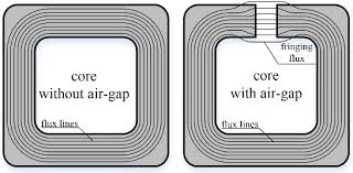
0.5 Tesla is a large magnetic field; you are going to need a lot of current (or a lot of loops) if you want to get that high. A typical configuration for generating near-constant magnetic fields is using a "Helmholtz Coil" configuration; you might find this type convenient. Another common configuration is using a "C" shape with a gap, kinda like the picture below (with coils wrapped around the C shape there)

enter image description here

$\endgroup$
1
  • $\begingroup$ Thanks for your comments, please see the diagram I have added. I think that this is similar to the C-core with a gap you suggested. Do you think it will be suitable? $\endgroup$
    – ab138
    Commented Oct 27, 2015 at 10:07

Your Answer

By clicking “Post Your Answer”, you agree to our terms of service and acknowledge you have read our privacy policy.

Not the answer you're looking for? Browse other questions tagged or ask your own question.