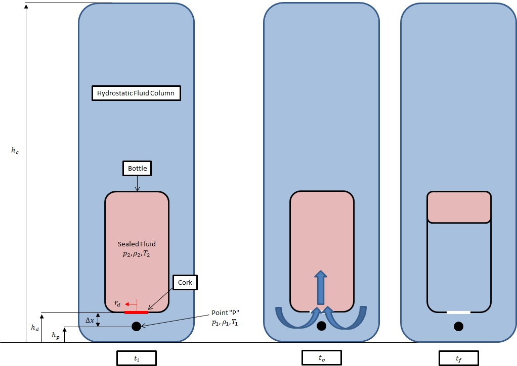
Suppose I cork an empty wine bottle sealing in the gaseous air at 1 atmosphere pressure. I then submerge the bottle in a fluid column as shown on the LHS of the figure below. The pressure at point "p", denoted as $p_1$, is much greater than the pressure in the wine bottle; the wine bottle keeps the air inside at 1 atmosphere pressure. (So $p_1>>p_2$). The point "p" is a "small" distance $(\Delta x)$ away from the bottle opening/cork. The bottle opening is circular with a radius $r_d$. If I were able to instantaneously remove the cork at $t_o$,
How would the pressure at point p change with time until the system came to equilibrium (at $t_f$)?
How would one go about estimating the evolving pressure at point p as a function of time? (from the most simplistic model to more sophisticated models)
Edit 1
Initially I think the problem may be analyzed using some form of the energy (or mechanical) balance equation (where the fluid column's fluid can be considered incompressible, slightly compressible, or compressible), some form of a nozzle or orifice equation, and the ideal or real gas law.
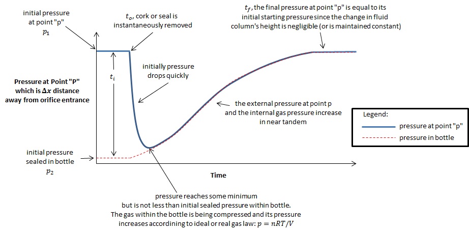
Currently, I envision the pressure at point "p" to respond as shown in the image below:
Edit 2
I made an attempt based on @ChesterMiller's answer, but took a bit of more simplistic approach. I would like to describe what I did and show my results. In turn I would like to kindly ask for critiques in what I had done and how I may improve the physical model.
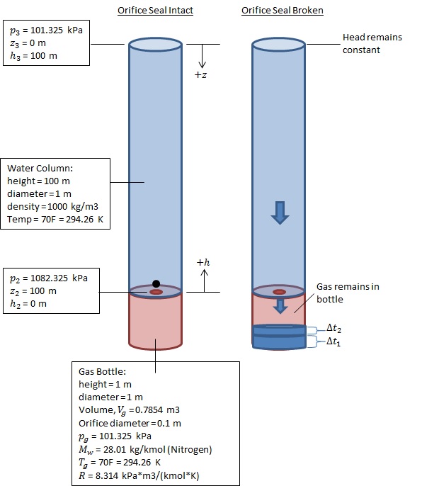
I re-imagined the physical setup of the system as shown on the LHS of the figure below. Noted on the figure are the liquid column's and gas bottle's properties.
The pressure just upstream of the orifice while the seal was intact was calculated as $$\tag{1} p_2=p_3+\rho_2 g z_2$$
The mass and moles of gas sealed in the bottle was calculated using the ideal gas law, where $$\tag{2} pV=nRT$$ $$\tag{3} n=m/M_w$$
So $m=0.911$ kg and $n=0.03253$ kmol.
The RHS of the image below shows how the liquid was assumed to enter and occupy the gas bottle. The gas was assumed to remain in the bottle (as it would as shown in the previous image above) and would compress as the bottle fills with the liquid. The liquid column height is assumed to remain constant and the liquid velocity at the top of the column ($\vec v_3$) is assumed to be zero (0 m/s).
To start I calculated the liquid's velocity entering the bottle just as the seal is broken, at time $t=0$ s. I assumed the pressure just upstream of the orifice, $p_2$, instantaneously decreased to the atmospheric gas pressure, 101.325 kPa, which is the pressure just inside the bottle at the other side of the orifice. The liquid's velocity was calculated using Bernoulli's Equation, $$\tag{4} p_3+0.5\rho_3 \vec v_3^2+\rho_3gh_3=p_{2,new}+0.5\rho_2 \vec v_{2,new}^2+\rho_2gh_2$$
The volumetric flow rate was calculated as $$\tag{5} Q=\vec v_{2,new}A_{orifice}$$ where $A_{orifice}=\pi (0.1 m)^2 /4 = 0.007853.. m^2$
From this point I chose a time increment of $\Delta t = 0.07 s$ (through some trial and error), and then iteratively followed these 7 calculations steps:
Calculate the volume of liquid that has entered the bottle: $V_{l,enter}=Q*\Delta t$.
Calculate the new volume of compressed gas: $V_{g,new}=V_{g,old}-V_{l,enter}$.
Calculate the new compressed gas pressure: $p_{g,new}=\frac{nRT}{V_{g,new}}$.
Set the pressure just upstream of the orifice, $p_2$, equal to the new compressed gas pressure.
Use the Bernoulli Equation to calculate the entering liquid's new velocity, $v_{2,new}$, based on the new outlet pressure, $p_2$ (or $p_{g,new}$).
Calculate the new volumetric flow rate: $Q=\vec v_{2,new}A_{orifice}$
Go back to step 1.
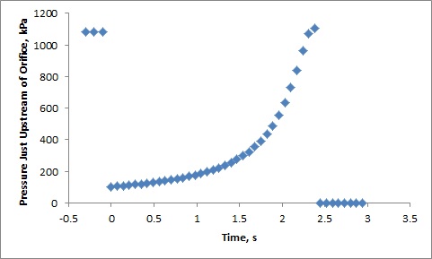
Following this procedure I found the pressure just upstream of the orifice to evolve in time as shown in the plot below:
If there are any erroneous steps taken in the above what are they? How might I improve this model?
Edit 3
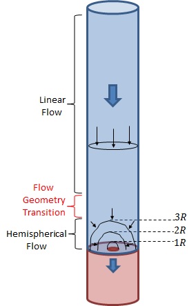
Envisioning converging hemispherical flow just upstream of the orifice, see image below, I have attempted to calculate the pressure within the liquid column as the gas bottle is filled over time.
The calculation procedure used was as follows:
- Calculate the orifice liquid velocity at t=0s using Bernoulli (Eqn (4)) assuming $p_2=p_g$ at the instant the seal is broken.
- Calculate the volumetric flow rate entering the gas bottle using the orifice liquid velocity and orifice area (Eqn (5)).
- Calculate the liquid velocity at varying distances $R$ above the orifice using Bernoulli assuming converging hemispherical flow. The surface areas of the hemispheres were calculated as $$\tag{6} A_{hemi}=2\pi R^2$$ and the velocities at each $R$ were calculated as $\vec v_R=Q/A_{hemi}$.
- Calculate the liquid velocity at the top of the liquid column, $\vec v_{3,new}$, where linear flow is assumed.
- Calculate the pressure at varying distances $R$ above the orifice using Bernoulli Equation and using the newly calculated variables: $\vec v_{3,new}$ and $\vec v_R$, and the potential energy at $R$ ($=\rho g R$).
- Set a discretizing time increment $\Delta t$.
- Calculate the volume of liquid that has entered the gas bottle.
- Calculate the newly compressed gas's volume.
- Calculate the newly compressed gas's pressure.
- Set the pressure at the orifice equal to the newly compressed gas's pressure.
- Using Bernoulli, calculate the new orifice liquid velocity using the newly compressed gas's pressure as the outlet pressure, and include the liquid velocity at the top of the liquid column. (Assume the pressure at the top of the liquid column is constant).
- Go back to Step 2.
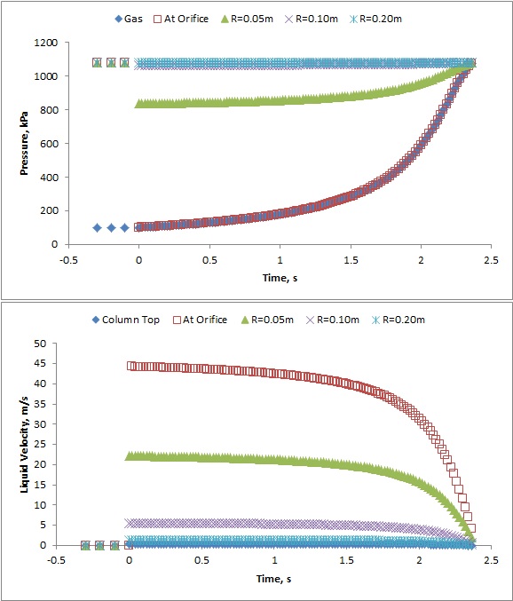
Below are two plots of the output from the calculations just described. The top plot shows pressure while bottom plot shows liquid velocity within the system as a function of time.
These plots/calculations show that the pressure one orifice diameter (R=0.10m) above the orifice is essentially the pressure one would calculate for the static condition. Only a significant pressure drop occurs at half an orifice diameter (R=0.05m) above the orifice.
I have noticed that changing the orifice diameter does not change the fluid velocity, rather, it changes the volumetric flow rate and therefore the time to fill the gas bottle. This result was a tad surprising and I wonder if this is an artifact on one or more of the assumptions I have made up to this point.
Again, I would like to kindly ask for critiques in what I had done and how I may improve the physical model.

