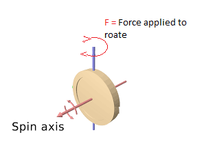
As we try to change direction axis of flywheel which is rotating on his own spin axis, feel a force which resist this change. So how can I calculate required minimum force to change direction of axis when we rotate at any angle. Check below:
-
$\begingroup$ You will need a torque to change the direction of the angular velocity of the flywheel. $\endgroup$– FarcherCommented Oct 3, 2016 at 10:19
-
$\begingroup$ what will be magnitude of that torque/force in form of flywheel mass, angular velocity and angle of changing axis direction ? $\endgroup$– SushilCommented Oct 3, 2016 at 12:00
2 Answers
The answer to your question is that there is no minimum force required to produce the required rotation.
What you need is a torque to start the flywheel rotating about the vertical axis and then at an appropriate time when the required angle is reached you need to switch off the torque.
The size of the applied torques and hence forces will depend on how rapidly you wish to change the angle.
The larger the torques and forces the faster will be the change.
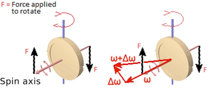
In the left hand diagram the torque $\tau$ is provided by a couple of magnitude $Fd$ where $d$ is the perpendicular distance between the lines of action of the two forces.
Now you might think that the directions of the forces (parallel to the vertical axis about which you wish to rotate the flywheel) and hence the torque is incorrect; it is not and for many totally counter-intuitive.
I have omitted the vector notation in my diagrams to make them clearer.
In the right hand diagram the angular velocity of the flywheel is $\vec \omega$ and you want to rotate the flywheel about the vertical axis so that its new angular velocity is $\vec \omega +\Delta \vec \omega$ with the magnitudes of both these angular velocities the same.
The initial angular velocity, the final angular velocity and the change in angular velocity $\Delta \vec \omega$ are all in a plane which is orthogonal to the axis of rotation.
Now the direction of the change of angular velocity represents a rotation which is clockwise (right hand grip rule) when look from thr right of the diagram and this is also the direction of the torque provided by the couple.
So you apply a torque to the system, allow the flywheel to rotate an appropriate amount and then switch off the torque.
Applying a larger force/torque will get the flywheel to the final position faster.
In fact the flywheel is a acting like a gyroscope undergoing precession which Professor Lewin calls the most non-intuitive part of mechanics and I suggest you view this video from about 14:00 for further insight?
In the video one of the forces producing the torque on the bicycle wheel is the downward weight of the wheel and the other is the upward force exerted by the rope on the axle of the wheel.
Solve this by analogy with a translating body (not rotating). Its linear momentum $p$ is:
$$p=mv$$
With $m$ the mass and $v$ the linear velocity.
Take the derivative to time of both sides:
$$\frac{dp}{dt}=m\frac{dv}{dt}=ma=F$$
For a purely rotating body the angular momentum vector is $\vec{L}$:
$$\vec{L}=I\vec{\omega}$$
Where $\vec{\omega}$ is the angular velocity vector and $I$ the moment of inertia about the axis of rotation.
Take the derivative in time of both sides:
$$\frac{d\vec{L}}{dt}=I\frac{d\vec{\omega}}{dt}=\vec{\tau}$$ Where $\vec{\tau}$ is the torque vector required to effectuate a change in direction of the angular momentum vector $\vec{\omega}$.
In scalar notation we can write:
$$\tau=\alpha I$$
Where $\alpha$ is the rate of change of direction of the $\vec{\omega}$ vector in $\mathrm{radians/s}$. If you want the flywheel to change its plane of rotation only slowly then only a small torque is needed but faster changes require higher torque.
Note that we cannot, as you intimate in your picture, apply force to the axis: only torque can make the axis turn.


