1
$\begingroup$

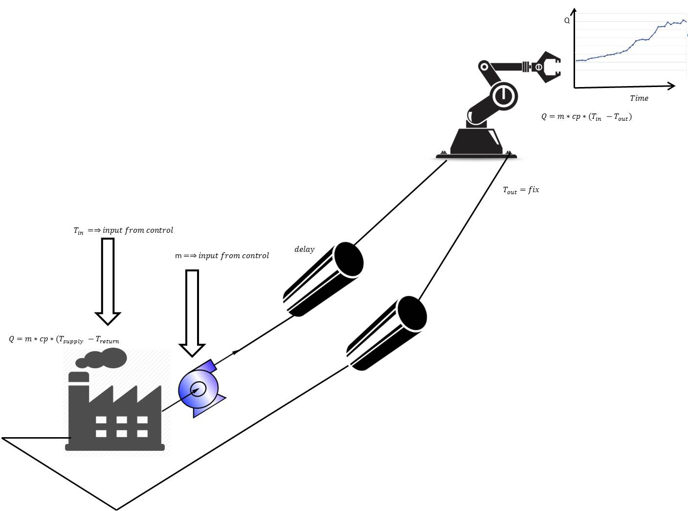
I want to model a heating system in an industrial hall. The system consists of: a heating plant, a pump, 2 pipes (each pipe is 500meters long) and a machine tool. The required heat for the machine-tool is given. I assume the heating plant and the pump as ideal (input to the pump = mass flow). The return-temperature from the plant is also constant. In a first test I want to set the delay of the pipe to a constant time (not depending on the mass flow).

The goal is to write this system as set of differential and algebraic equations with the inputs "Tin and mass flow". My question: Is this even a system of differential-equations? How could I include the delay of the pipe into the equations? Is there (in a next step) a simple equation for the pipe to catch the following behavior: If there is a change on the Temperature at the inlet, the outlet-temperature should change as a function of: geometry of the pipe and mass flow. enter image description here
Thank you very much for your help.

$\endgroup$
6
  • $\begingroup$ What do you understand by 'the delay of the pipe'? W/o insulation both pipes will lose heat, of course. $\endgroup$
    – Gert
    Commented Apr 3, 2016 at 13:17
  • $\begingroup$ @Gert Thank you for the comment: If the plant increases the temperature, it take some time till the temperature increases at the machine-tool (i call this "delay"). For simplificatoins, the pipes are adiabatic. I want to describe the system in a very simplified way. $\endgroup$
    – Matias
    Commented Apr 3, 2016 at 13:33
  • $\begingroup$ $\dot{Q_{mt}}=\dot{m}c_p(T_{in}-T_{out})$ is the power used by the machine tool. Since as there are no heat losses in the pipes, that power is what the heat plant needs to deliver to maintain all temperatures constant. Since as mass throughput $\dot{m}$ is constant, $\dot{Q_{hp}}=\dot{m}c_p(T_{out}-T_{in})$. There's nothing to model here, really. Heat out = Heat in. $\endgroup$
    – Gert
    Commented Apr 3, 2016 at 13:52
  • $\begingroup$ @Gert thank you very much! What if I adopt the model: $ heatLossPipe = function(constant, Tin , Tambient)$ and I want to control eiher the massflow or the temperature (if the required heat of the machine change). $\endgroup$
    – Matias
    Commented Apr 3, 2016 at 18:38
  • $\begingroup$ For a thin-walled pipe transporting a liquid, with convective losses only, the approx. model is $T_{out}=T_{amb}+(T_{In}-T_{amb})e^{-\alpha L}$ with $\alpha=\frac{\pi Dh}{\dot{m}c_p}$ and $h$ the Heat Transfer Coefficient of the pipe. The higher the mass flow the more the system is invariant to heat withdrawn by the machine-tool. $\endgroup$
    – Gert
    Commented Apr 3, 2016 at 19:18

1 Answer 1

0
$\begingroup$

Heat plant and Machine tool

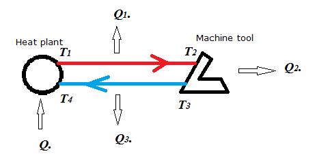
The heat balance of this system can be written as (in $\mathrm{W/s}$):

$$\dot{Q}=\dot{Q_1}+\dot{Q_2}+\dot{Q_3}$$

Where $\dot{Q_2}$ is the heat energy consumed by the machine tool and $\dot{Q_1},\dot{Q_2}$ heat losses resp. in the feed pipe and the return pipe.

Assuming constant mass flow $\dot{m}$ and specific heat capacity $c_p$ of the heat fluid, then:

$$\dot{Q_2}=\dot{m}c_p(T_2-T_3)$$

If we assume both pipes identical, thin-walled and with convection losses only, then:

$T_2=T_{amb}+(T_1-T_{amb})e^{-\alpha L}$

$T_4=T_{amb}+(T_3-T_{amb})e^{-\alpha L}$

Where $\alpha=\frac{\pi Dh}{\dot{m}c_p}$

With $D$ the pipe diameter, $L$ the pipe length, $h$ is the heat transfer coefficient of the pipe and $T_{amb}$ is the ambient temperature.

It can also be shown that:

$$\dot{Q_1}=\dot{m}c_p(T_1-T_{amb})(1-e^{-\alpha L})$$

And:

$$\dot{Q_3}=\dot{m}c_p(T_3-T_{amb})(1-e^{-\alpha L})$$

So:

$$\dot{Q}=\dot{m}c_p(T_1-T_{amb})(1-e^{-\alpha L})+\dot{m}c_p(T_3-T_{amb})(1-e^{-\alpha L})+\dot{m}c_p(T_2-T_3)$$

Of course, also:

$$\dot{Q}=\dot{m}c_p(T_1-T_4)$$

$\endgroup$

Your Answer

By clicking “Post Your Answer”, you agree to our terms of service and acknowledge you have read our privacy policy.

Not the answer you're looking for? Browse other questions tagged or ask your own question.