9
$\begingroup$

In a single slit experiment, the fringes are not equally spaced and aren’t of equal widths—the central maximum is the widest, the secondary maxima grow narrower and narrower outward, and the minima grow wider and wider outward.

enter image description here

In a double slit interference pattern, the fringes are equally spaced and of equal widths.

enter image description here

With a diffraction grating (lots of slits), the fringes are highly focused, with small widths and unequal spacing.

enter image description here

What are the reasons for the differences in fringe spacing and widths as the number of slits increases, specifically in each of the three scenarios I’ve presented above?

$\endgroup$
1
  • $\begingroup$ Other than the central bright spot a single slit will produce an equally spaced fringe pattern. Also Young's original slit experiment was not a double slit but a single human hair. The light passed along the two outer edges of the hair and produced an equally spaced fringe pattern. I do this all the time with laser and different gauge guitar strings. A singe edge (not a slit) will produce a fringe pattern with unequal spacing. $\endgroup$ Commented May 3, 2016 at 15:28

3 Answers 3

12
$\begingroup$

The first thing to note is that each of the slits produces a diffraction pattern the width of which is controlled by the width of the slit and the wavelength of the light.
The amount of light travelling from a slit in a particular direction is controlled by the diffraction pattern due to a single slit.
The light waves from each of the slits superpose (interfere) and produce an interference pattern.
The intensity of the fringes produced by the interference of light from the slits is modulated by the diffraction pattern produced by each of the slits.
That is why the intensity of the interference fringes deceases as the order of the fringes increases.


So here is the modulated interference pattern for one slit, two slits, three slits and five slits with all slits the same width and with the same slit separation.

enter image description here

Note the modulation of light intensity of the interference fringes by the diffraction envelope.
Also note that the separation of the principal maximum for the 2, 3 and 5 slit arrangement is the same. The spacing of the principal maxima is controlled by the separation of the slits $d$ and the wavelength of the light $\lambda$ The condition for the $n^{\text{th}}$ principal maximum is $n\lambda = d \sin \theta_n$.
You would have met this equation when studying the diffraction grating but it is the same equation for any number $N$ of slits provided that you are dealing with the principal maxima.


When two slit interference is studied the angle $\theta$ is small (< 0.1 radian or < 5$^\circ$) and so the approximation $\sin \theta \approx \theta$ is a good one.

So the condition for a maximum becomes $n\lambda = d \theta_n$ which results in the fringes appearing to be equally spaced.

When using the diffraction grating because the slit separation is small compared with that of the normal 2 slit arrangement the angles at which there are maxima are large.
So the small angle approximation cannot be made and the fringes are not equally spaced.


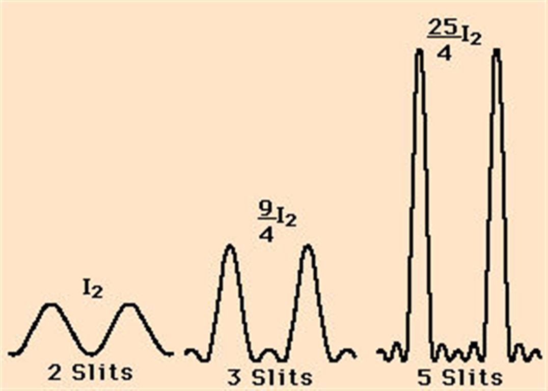
The other striking thing about the patterns for 2,3 and 5 slits is that the principal maxima get narrower as the number of slits increases and there are also in between the principal maxima much less intense subsidiary maxima.
What is shown by the next diagram is that as well as the principal maxima getting narrower they at the same time get brighter.
enter image description here

What is happening is that as the number of slits is increased the amount of light coming through the slits is increased and at the same time the light is being channelled into a smaller angular width (the fringe width).
Ignoring the diffraction envelope for 2 slits the intensity of a principal maximum $I_2 \propto (2A)^2$ where $A$ is the amplitude of a wave from a single slit.
For 3 slits $I_3 \propto (3A)^2$ and for five slits $I_5 \propto (5A)^2$.

So in a diffraction grating set up if the number of number of slits being used is reduced, say half the grating is covered up with black paper, the interference pattern would become less bright and the width of the principal maxima would increase.


Your three images are not comparing like for like.
For example the double slit pattern in the middle would appear to have slits which are much narrower than the slit used for the single slit pattern.
The reason for this inference is that the width of the diffraction envelope modulation of intensity is much broader in the second diagram than the first.
The last image of the pattern from a diffraction grating probably shows a much greater angular range than for the middle image because it shows the unequal spacing of the fringes.
It also shows that probably the width of the slits in the diffraction grating are much smaller than those in the two slit arrangement because there seems to be hardly any evidence of diffraction envelope modulation of intensity over a very wide angular range for the diffraction grating picture.


Although all the intensity graphs can be derived mathematically it is perhaps more informative to use phasor diagram to explain what is happening.
To make the analysis easier I have ignored the effect of the diffraction envelope.

For three slits you have the superposition of waves from three coherent sources each of amplitude $A$.

enter image description here

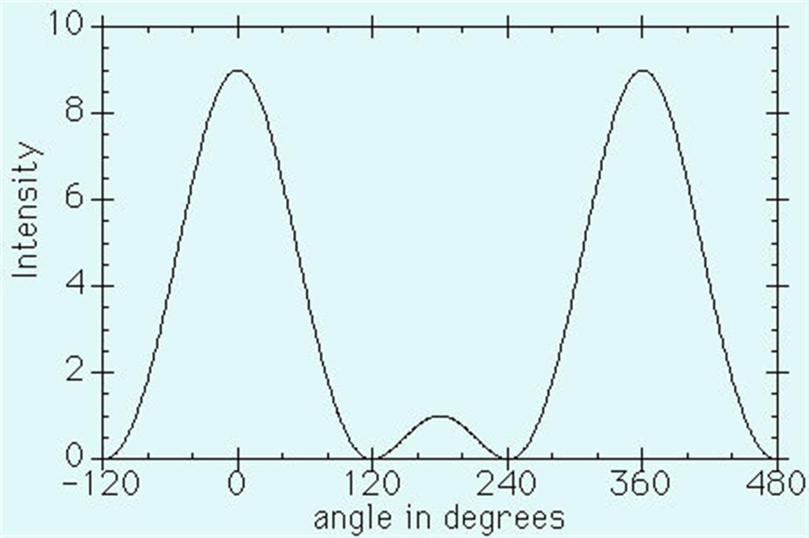
When $\theta = 0^\circ$ the three wave then the phase difference between the waves is zero and so when they overlap they produce a resulting amplitude for a principal maximum of $3A$. This is the $n=0$ fringe.
The same thing happens when the phase difference is $360^\circ$ which is a path difference of $\lambda$. This again results in a principal maximum of amplitude of $3A$. This is the $n = \pm 1$ fringe.

When the phase difference is $180^\circ$ which is a path difference of $\frac \lambda 2$, there is a secondary maximum of amplitude $A$.

For phase differences of $120^\circ$ and $240^\circ$ which correspond to path differences of $\frac {\lambda}{3}$ and $\frac {2\lambda}{3}$ the resultant amplitude is zero. There is a minimum in those positions.
enter image description here

So in the space between adjacent maxima for 2 slits there are now two minima and a secondary maximum. Thus the width of the principal maxima must have decreased.

Imagine how narrow and bright the principal maxima are for a diffraction grating if there are 5000 slits being used.

Finally. The separation of the principal maxima is controlled by the separation of the slits, the wavelength of the light and the order of the fringes whereas the width and intensity of the principal maxima is controlled by the number of slits.

$\endgroup$
2
  • $\begingroup$ good answer +1. I had to correct the little mistake about width of the maxima in my answer after reading yours ;) $\endgroup$ Commented May 3, 2016 at 14:38
  • $\begingroup$ @Farcher, your answer is so good there's no wonder why you have such high reputation! $\endgroup$
    – L. Levrel
    Commented May 25, 2016 at 19:55
0
$\begingroup$

TL;DR: the pictures given are at least inconsistent, if not wrong. It is not even clear what is plotted.

Let d be the separation of your slits (i.e. from centre to centre), a be the width of a slit and N be the number of slits. Then in the using a scalar theory of diffraction in the Fraunhofer limit, we can write the amplitude $\phi$ for an plane wave of wavevector $k$ coming in perpendicular to the grating:

$ \phi(\theta) \propto \text{sinc}\left( \frac{k sin(\theta) w}{2} \right) \times \frac{\sin\left( k \sin(\theta)\frac{ d N}{2} \right)}{\sin\left( k \sin(\theta) \frac{d}{2} \right)} $

If you are a pedant you may include an obliquity factor, but it will not matter for this argument. The intensity, which is what we see as the diffraction pattern is $|\phi|^2$.

where $\theta$ is the outgoing angle. Some more preliminaries: The sinc-term above is just an envelope scaling the interference peaks, so it will only make the peaks off-axis weaker. Let's assume all of them are visible still.

The fraction of the two sines is the interference term. It has 2 kind of maxima:

  • type 1 maxima when the $k \sin(\theta)\frac{ d}{2} = n \pi$ where $n\in \mathbb{Z}$.
  • type 2 maxima when the $k \sin(\theta)\frac{ d N}{2} = m \pi$ where $m\in \mathbb{Z}$ and m is not a multiple of N.

Now we can address the points in the question:

In a single slit experiment, the fringes are not equally spaced and aren’t of equal widths—the central maximum is the widest, the secondary maxima grow narrower and narrower outward, and the minima grow wider and wider outward.

What the OP calls "secondary maxima" is what I call "type 2 maxima" (chosen differently to avoid confusion). In the single slit case these are the only ones present. Now it depends on what is plotted in the picture. If it is plotted against the coordinate $x$ on a screen at distance $L$: $x=Lsin(\theta)$ then the type 2 maxima would be exactly equally spaced and have half the width of the type 1 maximum. So the picture is probably wrong. If we plot against $\theta$ there is some change in separation, but only at high angles.

In a double slit interference pattern, the fringes are equally spaced and of equal widths.

The intensity of these maxima in the picture falls of continuously, so they must be type 1 maxima. Type 1 maxima are also equally spaced if plotted against $x$. They have equal widths. Type 2 maxima would have half that width. So the pictures are clearly wrong.

With a diffraction grating (lots of slits), the fringes are highly focused, with small widths and unequal spacing.

Conclusion from repeating the arguments above: small width, sure, unequal spacing, nope (maybe if you plot against $\lambda$, but that would be inconsistent with the spacing from the double slit).

I have explained all the features of the gratings the pictures are trying (and failing) to demonstrate, so please refer to my answer instead of the pictures.

$\endgroup$
-2
$\begingroup$

When you pay attention to the left or right area of your double slit experiment you will see at the end the typical intensity distribution of a single slit. So a multi-slit arrangement is nothing all as the sum of two single slits. Of course the intensity distribution depends from the distance between the two slits. Artfully created, one would see a clear distribution like in your case. Then bigger the distance, then more one see the single slit distributions.

Go a step back and reflect, that even behind an edge fringes appear. Move two edges closer and closer together one get the intensity distribution you describe. And multi-slits are the sum of all of the edges. To break it down, the question is, why there are intensity distributions behind edges.

The answer is simple. Photons are moving units with oscillating electric and magnetic fields. Then thinner the edges shape (for example eraser blade), then higher the electrostatic potential from the surface electrons of the edge. This electrons and the photons form a quantized field and the projection of this field are the intensity distributions behind the edge.

Such an explanation helps to understand why even single photons, emitted over time, form intensity patterns behind edges. The surface electrons are in motion and differ with their energy, the distance from the photons source to the edge differs and all this led to the intensity distribution.

$\endgroup$
0

Your Answer

By clicking “Post Your Answer”, you agree to our terms of service and acknowledge you have read our privacy policy.

Not the answer you're looking for? Browse other questions tagged or ask your own question.