2
$\begingroup$

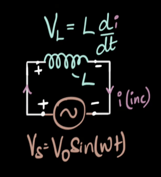
I was watching a Khan Academy video on the derivation of AC voltage across a pure inductor.

enter image description here

I understand the equation for the source alternating voltage. It's intuitive why the voltage is sinusoidal. However, the next step the derivation takes is equating the voltage of the inductor to the source voltage. This is extremely unintuitive, because if the voltage of the inductor were equal to the voltage of the source then there is no current in the circuit. This has left me very confused. How can we equate these two voltages but still have current? Is this because of Kirchoff's laws?

Edit: I understand that if we replace the inductor with the resistor current flows, but I don't see how this problem is analogous. Here the voltage of the inductor opposes the voltage of the source and if the voltages oppose each other and are the same magnitude then by definition the voltage has to be zero. If the voltage is zero, then by definition the current must be zero, so what is pushing the current? What is wrong with my intuition?

Furthermore, an inductor from my understanding creates a back voltage that tries to resist the change that caused it. So this back voltage opposes the voltage of the source and this is why I think the overall voltage must be zero and so the current zero.

$\endgroup$
8
  • $\begingroup$ "It's intuitive why the voltage is sinusoidal." The voltage is sinusoidal by definition. The tan colored circuit symbol represents a voltage source, and the equation below defines its voltage as a function of time. $\endgroup$ Commented Nov 8 at 3:20
  • $\begingroup$ "...equating the voltage of the inductor to the source voltage..." Again, by definition. The "+" terminal of the source and the "+" terminal of the inductor are connected by a wire. That makes them both belong to the same circuit node. Likewise, the two "-" terminals belong to a single circuit node. In an ideal circuit,* there can be no potential difference between different parts of the same node. [*Always assume that pedagogical circuit diagrams represent ideal circuits unless you are explicity told otherwise. ] $\endgroup$ Commented Nov 8 at 3:29
  • $\begingroup$ RE "if the voltage of the inductor were equal to the voltage of the source then there is no current in the circuit." would you say the same thing if the inductor was replaced with a resistor? $\endgroup$
    – The Photon
    Commented Nov 8 at 3:42
  • $\begingroup$ Not super confident but I believe the source of your confusion might be the fact that there's a voltage across the inductor and the battery and they don't add up to zero. Kirchoff's law states that the sum is zero, but for this you need to consider that the voltage drop across the load (inductor, resistor, whatever) is in the opposite direction compared to that of the battery. The sum is then zero. $\endgroup$ Commented Nov 8 at 3:44
  • $\begingroup$ A little off-topic but I feel like Kirchoff's law is stated in a way that's mathematically elegant but doesn't make sense to beginners. It's a bit easier to understand when you realize 'the voltage drop across the loads in a circuit is the same magnitude as the voltage across the power source' $\endgroup$ Commented Nov 8 at 3:50

1 Answer 1

1
$\begingroup$

if the voltage of the inductor were equal to the voltage of the source then there is no current in the circuit

This is not correct. The voltage and current for an inductor follow the relationship: $$v=L\frac{di}{dt}$$

So since there is a voltage $v$ across the inductor the current through the inductor changes at a rate $v/L$. Thus it simply is not true that the current is zero (more than momentarily).

$\endgroup$
2
  • $\begingroup$ Nice explanation. I pretty much understand this, but what is wrong with my intuition? I see the voltage of the inductor opposing the voltage of the cell, so the overall voltage must be zero. So how can there be current? $\endgroup$ Commented Nov 8 at 7:38
  • $\begingroup$ @QuinGardinerBax if your intuition were right then there would never be any current in any circuit because KVL says that the overall voltage is always zero. The voltage across a component and the current through a component are constrained by that component’s equation. $\endgroup$
    – Dale
    Commented Nov 8 at 12:09

Your Answer

By clicking “Post Your Answer”, you agree to our terms of service and acknowledge you have read our privacy policy.

Not the answer you're looking for? Browse other questions tagged or ask your own question.