3
$\begingroup$

I'm working on a finite element model as part of a line of research. Specifically I'm consider using vector finite elements (i.e 3 values x,y,z per node) to solve the Poisson equation in magneto-statics.

To ensure my code is functioning properly, the aim is to first reproduce the results set out in the following pair of papers:

N. Demerdash, T. Nehl and F. Fouad, "Finite element formulation and analysis of three dimensional magnetic field problems," in IEEE Transactions on Magnetics, vol. 16, no. 5, pp. 1092-1094, September 1980.
doi: 10.1109/TMAG.1980.1060817
keywords: {FEM;Finite-element method (FEM);Magnetic analysis;Finite element methods;Magnetic analysis;Magnetic fields;Coils;Closed-form solution;Inductance measurement;Maxwell equations;Geometry;Magnetic field measurement;Current density},
URL: http://ieeexplore.ieee.org/stamp/stamp.jsp?tp=&arnumber=1060817&isnumber=22843

    N. A. Demerdash, F. A. Fouad, T. W. Nehl and O. A. Mohammed, "Three Dimensional Finite Element Vector Potential Formulation of Magnetic Fields in Electrical Apparatus," in IEEE Transactions on Power Apparatus and Systems, vol. PAS-100, no. 8, pp. 4104-4111, Aug. 1981.
doi: 10.1109/TPAS.1981.317005
keywords: {Finite element methods;Magnetic fields;Magnetic flux;Transformer cores;Magnetic anisotropy;Perpendicular magnetic anisotropy;Magnetostatics;Magnetic field measurement;Integral equations;Student members},
URL: http://ieeexplore.ieee.org/stamp/stamp.jsp?tp=&arnumber=4111101&isnumber=4111054

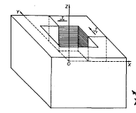
But I'm having difficulties defining the current density within my code. The model considers a aircored coil with rectangular cross section - akin to a rectangular current loop, but in 3D.

This is a fair representation of the type of system I would like to model

I know the cross sectional area of the coil region, the DC current carried by the coil as well as the number of turns of wire, the wire type is AWG #16. The winding height, inner length and outer length of the coil geometry all also known.

The overall simulation is a 'black box' simulation with the outer faces far enough away from the coil that approximately all of the flux density will be enclosed leading to Dirichlet boundary conditions on the outer surface.

My Attempt to Discretise the current density.

Simplistically, |J| = Current / Cross Sectional Area. For a loop with N_turns of wire, |J| = I N_turns / CA. In the 'bulk' of the coil, i.e where there is only current density in a single direction I think this may be a reasonable way to numerically describe the system with Jx/Jy = |J| in those sections.

The point I'm confused about is how to describe the current density in a discrete fashion in the corner regions where the two components are mixed together.

My best attempt for this region is to consider that |J| should be constant throughout the coil giving Jx = Jy = |J|/sqrt(2) at the corners however this doesn't account for the varying cross sectional area of the coil in the corner regions. All in all I feel like this is a simplistic description and I am subsequently missing parts of the model.

I know to first describe something well in a discrete fashion it is important to understand the continuous description however I'm struggling to find any resources/develop a framework to consider this approach either.

Any thoughts, directions or advice would be greatly appreciated.

Thanks for the time.

$\endgroup$
14
  • $\begingroup$ Do you calculate vector potential or magnetic field? $\endgroup$ Commented Nov 14, 2019 at 11:02
  • $\begingroup$ Vector potential $\endgroup$
    – LAPEMAG
    Commented Nov 14, 2019 at 13:52
  • $\begingroup$ I have adjusted my question to provide a little bit more information on the context and my attempts at a solution. $\endgroup$
    – LAPEMAG
    Commented Nov 14, 2019 at 14:30
  • $\begingroup$ How do you describe the geometry of the winding? What boundary conditions are used? $\endgroup$ Commented Nov 15, 2019 at 10:17
  • $\begingroup$ The simulation is a black box simulation with Dirichlet boundary conditions on the outer faces of the mesh. I'm honestly not certain about the geometry of the winding however I am attempting to reproduce the model from literature, I'll edit the above again with additional information. $\endgroup$
    – LAPEMAG
    Commented Nov 18, 2019 at 8:32

1 Answer 1

3
$\begingroup$

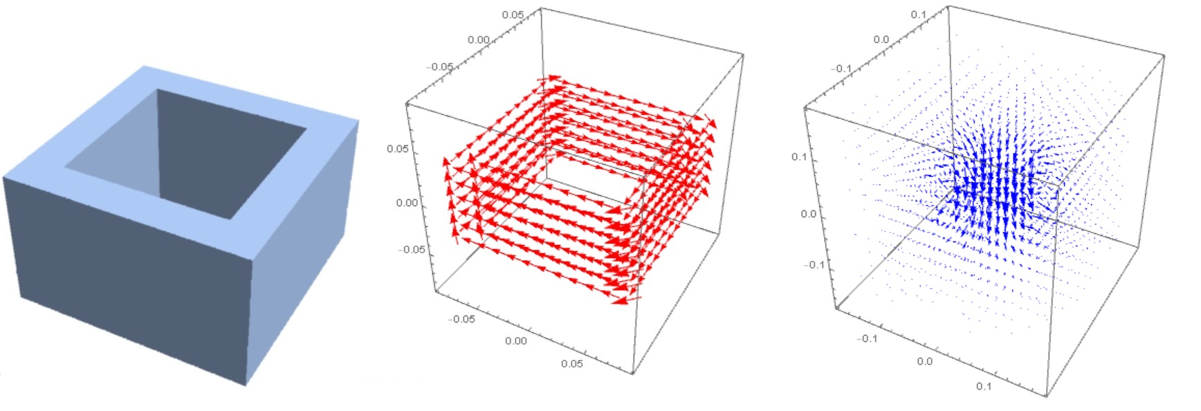
I used 3D FEM solver from Mathematica 12 to calculate the vector potential and magnetic field of a rectangular coil with a current of 20A. The number of turns = 861. The inner cross section is $10.42cm \times 10.42cm$, the outer cross section is $15.24cm \times 15.24cm$, coil height is $8.89 cm$. So we put in SI (input data) $$h=0.0889, L_1=0.1024, L_2=0.1524, I=20A,N=861$$

The average current density through the winding section is $$j_0=\frac {IN}{h(L_2-L_1)/2}$$ The magnetic permeability of copper and air is $\mu_1=0.999991\mu_0$ and $\mu_2=1.0000004\mu_0$ respectively, $\mu _0 =4 \pi 10^{-7}$. Since $\mu_1$ and $\mu_2$ differ little from $\mu_0$, we assume $\mu =\mu_0$ in the entire computational domain. We solve the following system of equations in a cube with side $L=4L_2$: $$\nabla \times (\nabla \times \vec A)=\mu_0 \vec j, \nabla.\vec A=0$$

On the surface of the cube we put $\vec {A}=0$.The current components in the region of winding are calculated as $$j_x(x,y,z)=j_0f(x,y,z),j_y=-j_x(y,x,z),j_z=0$$ here f=If[-y <= x <= y || y <= -x <= -y, Sign[y], 0]. Outside the winding region we put $\vec {j}=0$. Figure 1 shows the geometry of the coil, the distribution of current (red) and magnetic field (blue). Figure 1

To test the FEM, we used two models. 1. The integral equation for the vector potential (it is in all books on the theory of electromagnetic fields starting with Maxwell) $$\vec {A}=\frac {\mu_0}{4\pi}\int{\frac{\vec {j}}{r}dV}$$ 2. Closed Form Solution Algorithm (CFSA) -exact analytical formulas for the magnetic field of a rectangular loop (taken from article M. Misakian, “Equations for the magnetic field produced by one or more rectangular loops of wire in the same plane,” J. Res. Natl. Inst. Stand. Technol., vol. 105, pp. 557– 564, 2000.). Figure 2 shows the distribution of the vector potential in the plane $z=0$ (left), the magnetic field in the plane $y=0$ (center) and on the axis (right) in three models. We see that the FEM gives underestimated field values in the center of the coil. Figure 2 Code CFSA was tested on data from two articles:

  1. Dejana Herceg, Anamarija Juhas, and Miodrag Milutinov. A Design of a Four Square Coil System for a Biomagnetic Experiment,FACTA UNIVERSITATIS (NIˇS) SER.: ELEC. ENERG. vol. 22, no.3, December 2009, 285-292;

  2. Jiaqi Li and Shilong Jin. Magnetic Field Analysis of Rectangular Current-carrying Coil Based on ANSOFT Maxwell 3D Simulation, J. Phys.: Conf. Ser. 1168 052020,2019.

Compare the data CFSA with 3D FEM from Table 1 from the article N. Demerdash, T. Nehl and F. Fouad, "Finite element formulation and analysis of three dimensional magnetic field problems," in IEEE Transactions on Magnetics, vol. 16, no. 5, pp. 1092-1094, September 1980. doi: 10.1109/TMAG.1980.1060817.

Original table Figure 3

CFSA data versus 3D FEM Demerdash 1980 Figure 4 We see that FEM gives a good result for $B_x$ and $B_y$ but a big error in computation $B_z$.

Now let's compare modern FEM with what it was in 1980. I used 18,760 tetrahedron elements to split the cubic region. 1/8 of this number is 2345, which is slightly less than 2400 that used by Demerdash in 1980. The following table contains FEM 2019 and 1980 data. Figure5

$\endgroup$
5
  • $\begingroup$ The first equation for jo is the expression I was searching for. The other information is insightful though no particularly useful as I mentioned this is a coding exercise only at this point. $\endgroup$
    – LAPEMAG
    Commented Nov 25, 2019 at 7:56
  • $\begingroup$ Though I do query the current flow in the front left corner, it appears to be flowing out of the coil in the z direction..? $\endgroup$
    – LAPEMAG
    Commented Nov 25, 2019 at 7:57
  • 1
    $\begingroup$ No, this is only the appearance of a 3D projection on a plane. The current is within the winding. This is confirmed by direct integration in model 1 (Integral). The data of models 1 and 2 (CFSA) are the same. Model 2 is just a superposition of the 861 loop field. $\endgroup$ Commented Nov 25, 2019 at 10:33
  • $\begingroup$ It is a great answer. It's better to include the code in the answer. $\endgroup$ Commented Oct 7, 2020 at 7:09
  • 2
    $\begingroup$ @Gowiththewind It could be better to discuss code, for example, on mathematica.stackexchange.com/questions/230282/… $\endgroup$ Commented Oct 7, 2020 at 10:05

Your Answer

By clicking “Post Your Answer”, you agree to our terms of service and acknowledge you have read our privacy policy.

Not the answer you're looking for? Browse other questions tagged or ask your own question.