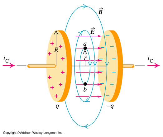
If in a flat capacitor, formed by two circular armatures of radius $R$, placed at a distance $d$, where $R$ and $d$ are expressed in metres (m), a variable potential difference is applied to the reinforcement over time and initially zero, a variable magnetic field $B$ is detected inside the capacitor. Neglecting the effects on board, at a distance $r$ from the symmetry axis of the capacitor, the intensity of $B$ varies with the law
$$\boxed{B(r)=\dfrac{kt}{\sqrt{(a^2+t^2)^3}}\,r} \quad r\leq R,\quad \tag{1}$$
where $a$ and $k$ are positive constants and $t$ is the time elapsed since the initial moment, expressed in seconds (s).
1. How can I prove the $(1)$?
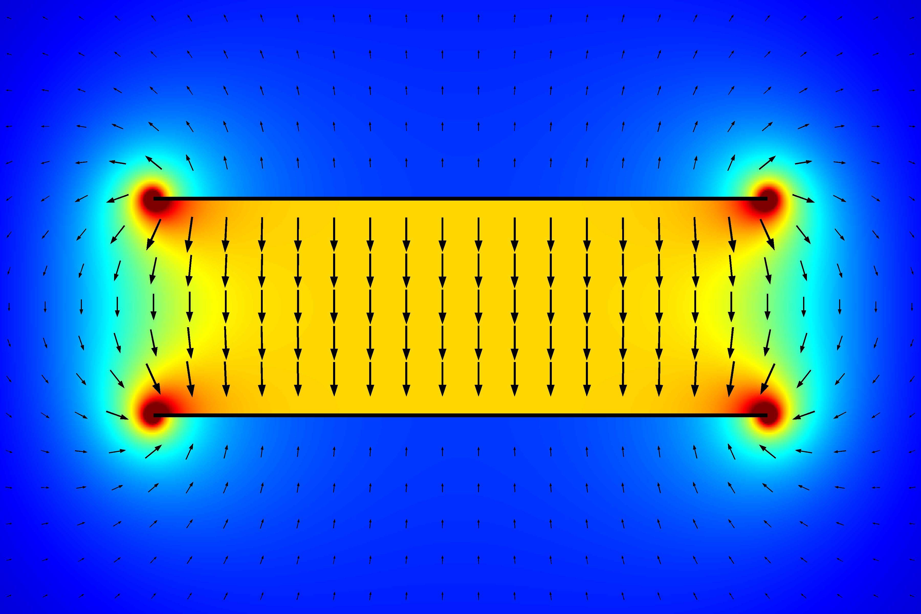
2. Why is the direction of the electric field $E$ within the capacitor that of the symmetry axis and are the lines of the magnetic field generated by the displacement current concentric circular lines, with center on the symmetry axis, and lie on planes parallel to the reinforcements and perpendicular to the symmetry axis?
(The image is taken from this link: Magnetic field from displacement currents in a capacitor, and an applied exterior magnetic field)
Does exists a mathematical explanation?
3. What happens when $r>R$?
My considerations. Obviously from the previous condition $\boldsymbol{\mathrm{E}}$ and $\boldsymbol{\mathrm{B}}$ are perpendicular to each point.
I have thought that from the fourth Maxwell equation in differential form. Hence we have:
$$\boldsymbol{\nabla}\times \boldsymbol{\mathrm{B}}=\epsilon_0\mu_0\frac{\partial \boldsymbol{\mathrm{E}}}{\partial t}+\mu_0\boldsymbol{\mathrm{J}}$$
where the fourth equation of Maxwell in integral form becomes the theorem of Ampère-Maxwell:
$$\oint_\ell \boldsymbol{\mathrm{B}} \cdot d\boldsymbol{\mathrm{l}}=\mu_0 I_{\mathrm{enclosure}}=\sum_k\mu_0I_k=\mu_0(I_s+I_c)$$ where with $I_s$ we indicate the sum of all the displacement currents and with $I_c$ all the conduction currents. Remember that displacement current is given by
$$I_s=\epsilon_0\mu_0\frac{\partial \boldsymbol{\mathrm{E}}}{\partial t}$$ and being $\boldsymbol{\mathrm{J}}=\boldsymbol{\mathrm{0}}$ (because in the capacitor is it does it present a magnetic field even in the absence of magnets and conduction currents). In the region between the armatures, the theorem takes the following form:
$$\oint_\ell \boldsymbol{\mathrm{B}} \cdot d\boldsymbol{\mathrm{l}}=\epsilon_0\mu_0\frac{\partial \boldsymbol{\mathrm{E}}}{\partial t}$$ i.e. the circuitry $\Gamma(\boldsymbol{\mathrm{B}})$ is:
$$\oint_\ell \boldsymbol{\mathrm{B}} \cdot d\boldsymbol{\mathrm{l}}\equiv\Gamma(\boldsymbol{\mathrm{B}})=\epsilon_0\mu_0\frac{d\Phi(\boldsymbol{\mathrm{E})}}{\partial t}.$$


