It is a matter of convenience: voltage and current in the wires are related to the electric and magnetic fields via the Maxwell equations - we can, find ones once we know the others. When we deal with a rectangular or cylindrical wave guide, dealing with electric and magnetic field is preferable, since the there is no clear way to define voltage and current in this case - e.g., voltage is measured between two points, and the choice of these two points in a cross-section of the wave-guide is somewhat arbitrary. For two parallel wires, voltage is straightforwardly defined as the potential difference between the two wires at the specified cross-section, whereas the electric and magnetic fields have a rather complex structure in the space between the wires.
Update
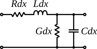
Current and voltage in a transmission line can be viewed in terms of Telegrapher's equations, where voltage stands as a proxy for the electric field (in the effective per-length capacitance), whereas the current is a proxy for the magnetic flux (in the effective per-length inductance).

(image source)
In either case, describing oscillations/waves requires two conjugate variables, because oscillator/wave equations are second order equations. For a harmonic oscillator these are position and momentum, for EM wave these are the electric and the magnetic field, whereas for a transmission line these are voltage and current. As previous paragraph shows, voltage and current can be related to the electric and magnetic fields, but used here as more practical variables for circuit engineering (see also Lumped-element model.)

