4
$\begingroup$

I am reading about inductors connected in A.C. Circuits. I understand mathematically that the current lags behind voltage. But what is the physical explanation for this?

My understanding:

As the emf of the alternating source increases, an opposing emf of equal magnitude is induced in the inductor due to self induction. But if this the case, how can current flow? One emf tries to push electrons one way and the other emf tries to push electrons the other way?

I came across a similar question here:If induced voltage (back-emf) is equal and opposite to applied voltage, what drives the current? but there were so many answers that I don't know what is right)

I hope that the answer to this question will help me figure out other questions like how current increases when the emf decreases.

$\endgroup$
2
  • $\begingroup$ The magnetic field in the inductor wants to maintain its steady state condition (see Lenz's Law for a closely related subject). Because of this, as the polarity in the AC circuit changes, the inductor "fights" this, and it takes time for the instantaneous emf of the circuit to change the magnetic field in the inductor. Due to this, the current in the inductor always lags the emf across the inductor. $\endgroup$ Commented Aug 19, 2018 at 1:10
  • $\begingroup$ @GokulakrishnanShankar I have added an answer to the question in the link that you have quoted which may help answer your question? physics.stackexchange.com/a/423571/104696 $\endgroup$
    – Farcher
    Commented Aug 19, 2018 at 16:08

5 Answers 5

3
$\begingroup$

The answer to your question lies in the fact that you are dealing with two different electric fields which are competing with one another and that the non-conservative electric field produced by the inductor owes its existence to a changing magnetic flux produced by a changing current in the circuit.
One electric field produced by the voltage source is trying to change the current and the other electric field produced by the inductor is trying to stop the change in current but the change in current has to happen because if it didn't the electric field produced by the inductor would cease to exist.

The definition of self-inductance $L$ is $L=\frac {\Phi}{I}$ where $\Phi$ is the magnetic flux and $I$ is the current.

Differentiating the defining equation with respect to time and then rearranging the equation gives $\frac{d\Phi}{dt} = L\frac{dI}{dt} \Rightarrow \mathcal E_{\rm L} = - L\frac{dI}{dt} $ after applying Farday's law where $\mathcal E_{\rm L}$ is the induced emf which is going to try and prevent any change in the current.

Consider a series circuit which consists of an alternating voltage source and an ideal inductor.
The alternating voltage source is trying to change the current in the circuit by varying the electric field in the circuit.
The inductor is trying to oppose any change to the current and hence the magnetic flux by producing a non-conservative electric field in opposition to the field produced by the voltage source.
The strength of the non-conservative field which will oppose the electric field trying to change the current in the circuit is determined by the rate of change of current in the circuit.
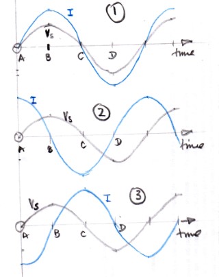
enter image description here

Suppose the current and the supply voltage are in phase with another as in graph 1.
Just after time A the electric field due to the supply voltage is increasing which leads to an increase in the current in the circuit.
The inductor needs to generate an electric field which tries to negate small electric field produced by the voltage source.
However, at this time the rate of change of current is a maximum.
At time B the electric field produced by the voltage source is large and to negate its effect the inductor must produce a large electric field in the opposite direction yet at this time the rate of change of current is near zero.

Suppose that the current leads the supply voltage by $90^\circ$ as in graph 2.
Just after time A the electric field due to the supply voltage is increasing which leads to an increase in the current in the circuit.
The inductor needs to generate an electric field which tries to negate small electric field produced by the voltage source.
The good news is that at this time the rate of change of current very small, but the electric field produced by the inductor would be in the same direction as the electric field produced by the voltage source.
At time B there is a large rate of change of current so that the inductor would produce a large electric field to negate the electric field produced by the voltage but again that field is in the wrong direction.

You could go on like this until you get to graph 3 where the supply voltage leads the current by $90^\circ$ and you will find that at all times the magnitude of the electric field produced by the inductor mirrors that produced by the voltage source but is opposite in direction.

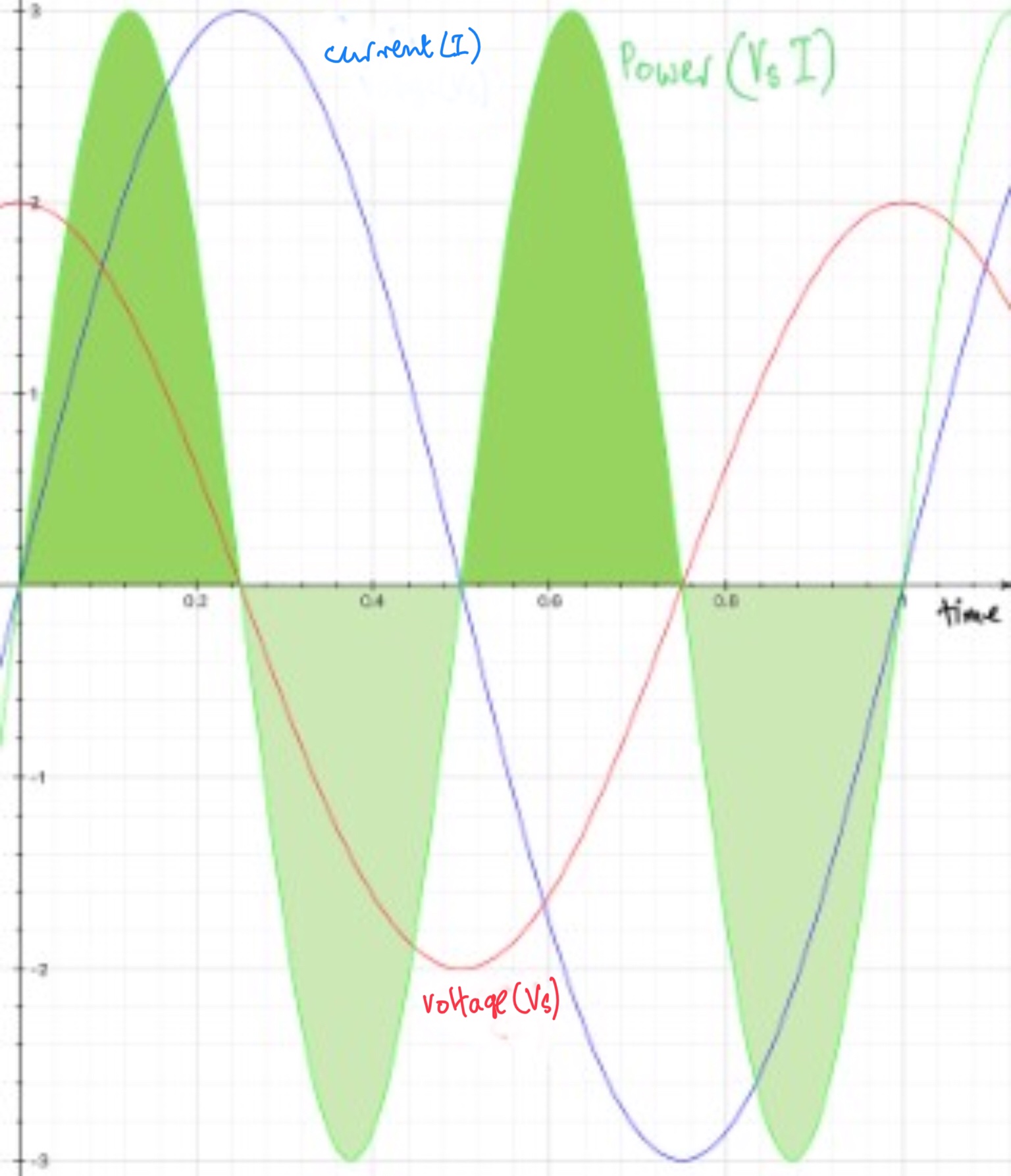
In terms of energy the graphs of supply voltage, current and power produced by the voltage source look like this. if the phase difference if $90^\circ$.
enter image description here

The darker green areas represent energy flowing from the voltage source to the inductor and the lighter green areas represent energy floring from the inductor to the voltage source.
A corresponding power graph for the inductor would be the mirror image of the one for the voltage source.

Overall the important thing to realise is that even if two emf in a circuit look as though they negate each other there can still be a transfer of energy between the two sources of emf.

$\endgroup$
4
  • $\begingroup$ But in the last graph (the coloured one), it looks like the current leads the voltage.... Am I getting it wrong? $\endgroup$ Commented Aug 28, 2018 at 15:10
  • $\begingroup$ @GokulakrishnanShankar You are correct and I have switch two labels in the graph to show the voltage leading the current. $\endgroup$
    – Farcher
    Commented Aug 28, 2018 at 15:25
  • $\begingroup$ Thanks a lot! I understand now... Just one last question: why "non conservative" electric field? $\endgroup$ Commented Aug 28, 2018 at 15:55
  • $\begingroup$ @GokulakrishnanShankar If the work done between two points is not independent of the path taken then the field is non conservative. Have a look at this video. m.youtube.com/watch?v=eqjl-qRy71w $\endgroup$
    – Farcher
    Commented Aug 28, 2018 at 17:34
2
$\begingroup$

As the emf of the alternating source increases, an opposing emf of equal magnitude is induced in the inductor due to self induction. But if this the case, how can current flow?

But the induced emf isn't there unless the current through the inductor is changing. From the Wikipedia article Inductance:

In electromagnetism and electronics, inductance is the property of an electrical conductor by which a change in electric current through it induces an electromotive force (voltage) in the conductor.

Your first sentence in your quote above is essentially correct but you must also understand that the opposing emf, due to self induction, implies that the current is changing.

For an ideal inductor with a non-zero voltage across, the current through can be finite only if the voltage across and the induced emf are equal in magnitude. Since the emf is zero when the current through is constant, it follows that when there is a voltage across the inductor, there is a changing current through.

You might find my answer here helpful.

$\endgroup$
2
  • $\begingroup$ 1) So in order for the induced emf to become equal to the voltage of the source, there must be current changing in the inductor, right? $\endgroup$ Commented Aug 19, 2018 at 3:17
  • $\begingroup$ @GokulakrishnanShankar, (1) in order for there to be any (induced) emf at all, the current must be changing and (2) the current must changing at just the right rate such that the induced emf has the same magnitude as the voltage of the source. $\endgroup$ Commented Aug 19, 2018 at 12:49
1
$\begingroup$

The mathematical explanation is

$$ V = L \frac{{\rm d}I}{{\rm d}t}$$

which is just the mathematical definition of the term inductor.

If you turn this around,

$$\frac{{\rm d}I}{{\rm d}t} = \frac{V}{L}$$

If this tells you that, for example if $I$ is negative, and you start applying a positive current, the current will only then start to trend positive. And it won't actually reach a positive value until some finite time after you've applied the positive voltage.

Then once current goes positive, the same thing happens when you apply a negative voltage --- you have to wait before you'll get a negative current.

$\endgroup$
1
$\begingroup$

imagine that the inductor is a mass, and the voltage is a force acting on that mass, and the current is the velocity of the mass.

we start with the mass (inductor) at rest, with velocity (current) equal to zero. you apply a force (voltage) to the mass (inductor). at the instant you apply that force (voltage), the velocity (current) of the mass (inductor) is zero. and as it then accellerates, the velocity (current) in the mass (inductor) still lags behind force (voltage).

$\endgroup$
0
$\begingroup$

Your question implies that the voltage across an inductor is equal to the difference between the applied voltage (emf) and the opposing voltage (back emf) and, since the back emf is equal to the applied voltage, the resulting voltage on the inductor should be zero.

In reality, if you apply some voltage to an inductor and actually measure it with a voltmeter, you'll see that the voltage is not zero, but is, in fact, equal to the applied voltage, which causes the current in the inductor to grow according to the familiar equation: $V_{appl}= L \frac {di} {dt}$.

So, although the concept of the "back emf" is very useful, it should not be treated as a real voltage, since that would lead to the incorrect conclusion that the net voltage across an inductor is always zero. It is not.

A possible mechanical analogy is Newton's second law, $F_{appl}=ma=m \frac {dv} {dt}$. We could call $ma$ a Back Force and treat it as a real force acting on a body in response to the applied force $F_{appl}$, in which case we could, mistakenly, conclude that the net force acting on a body is zero and, therefore, the body should not accelerate.

$\endgroup$
7
  • $\begingroup$ You are right that emf is not voltage, but unfortunately your analogy is misleading. It suggests that induced EMF is not a measure of additional force, but only a manifestation (acceleration) of the real forces measured by voltage (impressed force). But in fact in EM theory both voltage forces and induced electromotive forces are real and contribute to total force. In low ohmic resistance coil they largely cancel out though and the tiny difference is what makes the current accelerate/decelerate. $\endgroup$ Commented Mar 9, 2019 at 23:44
  • $\begingroup$ @JánLalinský "In low ohmic resistance coil they largely cancel out though and the tiny difference is what makes the current accelerate/decelerate." So, if the resistance was zero, the difference between the applied voltage and EMF would be zero and the current would not "accelerate" at all? $\endgroup$
    – V.F.
    Commented Mar 10, 2019 at 1:04
  • $\begingroup$ No, becase emf in ideal inductor is given by $-LdI/dt$, so if emf is non-zero, current will change in time. The lower the ohmic resistance of real coil, the lower the difference between emf and voltage needed for given $dI/dt$. $\endgroup$ Commented Mar 10, 2019 at 2:38
  • $\begingroup$ @JánLalinský You've said: "...the tiny difference is what makes the current accelerate...". According to this, if the difference between the applied voltage and EMF (L di/dt) is zero, the current won't accelerate. I am saying: L di/dt term (which is the difference between the applied voltage and IR) is what makes the current accelerate. The mechanical analogy of of this difference is the difference between the applied force and the friction and this difference would be responsible for the mechanical acceleration, ma. $\endgroup$
    – V.F.
    Commented Mar 10, 2019 at 12:48
  • $\begingroup$ no, you are misapplying my statement above (which was meant for a real coil) to the idealized case of zero ohmic resistance. Of course, non-zero emf alone implies non-zero current acceleration, regardless of what the difference between EMF and voltage is. But this does not mean that forces quantified by the term $LdI/dt$ alone make the current accelerate. It is the vector sum of both electrostatic forces (q. by voltage) and induced electric forces (q. by EMF) that make the current accelerate. In the ideal case of zero resistance, it is just that such difference needed is zero. $\endgroup$ Commented Mar 10, 2019 at 19:00

Your Answer

By clicking “Post Your Answer”, you agree to our terms of service and acknowledge you have read our privacy policy.

Not the answer you're looking for? Browse other questions tagged or ask your own question.