2
$\begingroup$

My problem is with a circuit containing a resistor of suitable resistance $R$ and a solenoid. Initially, a battery is connected which generated a current in the circuit and at $t=0$, the battery is disconnected from the circuit.

Now I need to find the current as a function of the time $i(t)$, for which I've used Kirchhoff's Voltage Law.

I know that the voltage drop across the resistor is $V=IR$, and the back EMF induced in the solenoid is $V=-L\frac{di}{dt}$ where $L$ is the self-inductance of the coil.

Now, I don't know how to determine the sign of voltage across the solenoid while traversing the loop. I mean, whether it's positive or negative..?

$\endgroup$
4
  • 1
    $\begingroup$ $L$ is a positive quantity. $\endgroup$
    – Siyuan Ren
    Commented Sep 30, 2012 at 10:40
  • $\begingroup$ @Ziv: Hello Ziv & welcome to Physics.SE. Please refer to our homework policy before asking such questions 'cause we discourage when users ask us to solve their homework questions..! Also, Please use the TeX resource in this site for indicating math codez... as the one I've suggested..! $\endgroup$ Commented Sep 30, 2012 at 11:05
  • 1
    $\begingroup$ @ Crazy Buddy Thanks, this question is not my homework, it is a general question about determining the sign of the voltage of the coil in any circuit and in any state of the circuit: I'm actually asking about what is the convention about the sign in general, and the problem above is just an example. and about the math format- I just needed to write these 2 miniature equations, which are actually Ohm's law and deductive EMF equation which are Known and not my own calculation, and learning how to use Tex would have taken me a long time, so I figured it will be understood $\endgroup$
    – Ziv
    Commented Sep 30, 2012 at 11:33
  • 2
    $\begingroup$ The homework tag is appropriate, but this question seems fine because it's asking about a concept, not asking for a solution or for someone to check the work. $\endgroup$
    – David Z
    Commented Sep 30, 2012 at 12:08

2 Answers 2

3
$\begingroup$

Actually, for electric circuits, the voltage across an inductor is

$v_L = L \dfrac{di_L}{dt}$

By the passive sign convention, the inductor current enters the terminal that is the more positive when $v_L>0$.

Here's what you do. Pick a direction for the inductor current by drawing an arrow pointing into one of the terminals. Label that arrow $i_L$. Now, place a plus sign at the terminal the current enters and a minus sign at the other terminal. This is the polarity of the inductor voltage $v_L$.

By the formula above, if the inductor current is increasing with time, $v_L>0$. If the inductor current is decreasing with time, $v_L < 0$.
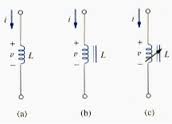
enter image description here

You can't pick the "wrong" direction or polarity. The signs will take care of themselves.

Is you problem similar to this one?
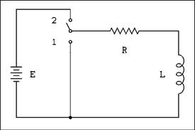
enter image description here

When the switch has been in position 2 for a long time, the series electric current is constant and clockwise through the resistor, inductor, and source. Since there is only one current, the series current, let's just label that $i$ and have the arrow pointing into the left end of the resistor.

According to the passive sign convention, the polarity of our voltage variables, $v_R, v_L$ have the positive sign at the left end of the resistor and the top end of the inductor.

Since the current is constant, $v_L = 0$, thus $i=E/R$ and $v_R = E$ for $t<0$.

If at $t=0$ the switch is (instantaneously) changed to position 1, The current through the inductor must be same at $t=0+$ as at $t=0-$, i.e., the current through the inductor is continuous.

With the same current as before, the voltage across the resistor $v_R(0+) = E$. But now, this means that $v_L(0+) = -E$ by KVL (sum of voltage drops around a closed loop is zero). This implies that the current through the inductor is decreasing (negative time rate of change) which is what you should expect!

We have the initial condition, $i(0+) = E/R$, and the form of $i(t)$ is the well known decaying exponential:

$i(t) = \dfrac{E}{R}e^{-\frac{t}{\tau}}, \tau = \dfrac{L}{R}, t>0$

$\endgroup$
10
  • $\begingroup$ Yes, this is exactly the circuit I meant in my example $\endgroup$
    – Ziv
    Commented Oct 1, 2012 at 7:40
  • $\begingroup$ @Ziv, have you worked it out? $\endgroup$ Commented Oct 1, 2012 at 12:04
  • $\begingroup$ No, I'm still trying to understand. My Lecturer says that I can arbitrarily determine the direction of the current in any circuit (any circuit and at any state) - is this what you meant by the arrow ? $\endgroup$
    – Ziv
    Commented Oct 1, 2012 at 13:20
  • $\begingroup$ When I'm trying to solve circuit problems I'm marking points of potential between components, so that the voltage of/(on?) a component is the difference between potential points that are at the ends of it. $\endgroup$
    – Ziv
    Commented Oct 1, 2012 at 13:25
  • $\begingroup$ Case one: the battery is part of the circuit: I choose the current's direction to be clockwise, and the current is increasing in time. And let's say that I have 3 points of potential: V1 between the battery and the resistor, V2 between the resistor and the coil, and V3 between the coil and the battery. Then now: V(resistor)= V1-V2 = IR; V(coil)= V2-V3= Ldi/dt; V(battery)= V (Known) $\endgroup$
    – Ziv
    Commented Oct 1, 2012 at 13:32
2
$\begingroup$

If you want to go more in depth. The negative sign in the equation, $v(t) = -L\frac{\mathrm {d}i}{\mathrm{d}t}$ comes from the assumption of active convention, not passive convention. In a voltage source the electromagnetic field comes from the positive end of the voltage source. Therefore, it re-enters the voltage source from the negative end and comes back into the circuit from the positive end.

Then the entry point is negative and the exit point is positive so the energy or the work done by the electromagnetic field depends on the final voltage minus the initial voltage. Since the initial voltage is negative and a negative number multiplied by a negative number is positive, the final voltage of the voltage source is positive. In this case, the negative sign does apply because current creates an induced magnetic field in the inductor.

For instance, if the current is increasing then the magnetic field wants to increase in the direction of the current, but the inductor doesn't like that (look up right hand rule for more explanation). Therefore, it creates an induced magnetic field in the opposite direction. Because the negative derivative of the change in magnetic flux (the area of the magnetic field between the loops of the inductor) with respect to time is equal to voltage, the voltage is negative in the inductor. This derivative is actually the same as $-L\frac{\mathrm{d}i}{\mathrm{d} t}$ except the derivative of magnetic flux is multiplied by the number of loops in the inductor.

If you assume the passive convention, then you don't need to worry about the negative sign because the voltage source would be negative and the inductor voltage would be positive so the current across a resistor, for instance, in a Resistor/Inductor Circuit would gradually increase since the inductor "holds" the voltage back from the resistor. In other words negative voltage from the source plus positive voltage from the inductor (using Kirchoff's Voltage Law) creates a smaller voltage in the resistor.

I hope this satisfies your curiosity.

$\endgroup$

Your Answer

By clicking “Post Your Answer”, you agree to our terms of service and acknowledge you have read our privacy policy.

Not the answer you're looking for? Browse other questions tagged or ask your own question.