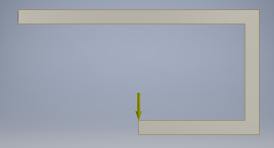
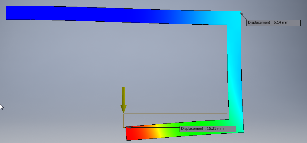
Although the beam that's perpendicular to both parallel beams doesn't deform much axially, it does bend, which affects the deformation of the end of the lower beam in a non-neligible way. For this reason, you can't just idealize the horizontal beams as two directly connected cantilever beams (which you've probably figured out).
In the past, I was able to analytically calculate the deflection of connected segments of microfabricated silicon beams using Castigliano's theorem. As you suggest, it comes down to the "force absorbed" (i.e., the strain energy) in the structure. The key idea is that the additional strain energy absorbed due to an infinitesimal additional deflection is exactly equal to the force and vice versa.
The following holds for small displacements of long beams; if you want to study large displacements, look at Larry Howell's work on compliant joints, which is substantially more complex but very thorough.
Number the beams $1$, $2$, and $3$ moving down. Working up, beam $3$ undergoes a bending moment that ranges from $0$ on the left to $FL_3$ on the right. Beam $2$ undergoes an axial load of $F$ and a constant bending moment of $FL_3$. Beam $1$ undergoes a bending moment that ranges from $FL_3$ on the right to $F(L_3-L_1)$ on the left. (I've ignored all transverse loads.)
The strain energy for each segment is $U=\int_0^L\frac{P(x)^2}{2AE}dx+\int_0^L\frac{M(x)^2}{2EI}dx$ with stiffness $E$, cross-sectional area $A$, and moment of inertia (i.e., second moment of area) $I$. Thus,
$$U_1=\int_0^{L_1}\frac{F^2(L_3-x_1)^2}{2E_1I_1}dx_1=\frac{F^2}{6E_1I_1}(3L_3^2L_1-3L_3L_1^2+L_1^3)$$
$$U_2=\int_0^{L_2}\frac{F^2}{2E_2A_2}dx_2+\int_0^{L_2}\frac{F^2L_3^2}{2E_2I_2}dx_2=\frac{F^2L_2}{2E_2A_2}+\frac{F^2L_3^2L_2}{2E_2I_2}$$
$$U_3=\int_0^{L_3}\frac{F^2x_3^2}{2E_3A_3}dx_3=\frac{F^2L_3^3}{6E_3I_3}$$
Now we apply $\delta=\frac{\partial U}{\partial F}$ and assume uniform materials and beam cross sections for simplicity:
$$\delta/F=\frac{1}{3EI}\left(L_1^3+3L_1L_3^2-3L_3L_1^2+3L_3^2L_2+L_3^3\right)+\frac{L_2}{EA}$$
which is the compliance of the assembly with respect to that particular load location.
Now, I thought it would be interesting to brute-force the deflection at the bottom by calculating all the individual deflections and rotations, again assuming small displacements and long beams. The downward deflection at the load application point is going to be the combination of the downward deflection of beam $1$ (which is $\frac{FL_1^3}{3EI}$ from the downward load and $-\frac{FL_3L_1^2}{2EI}$ from the bending moment), plus the axial deflection of beam $2$ (which is $\frac{FL_2}{AE}$), plus the deflection of beam $3$ (which is $-\frac{FL_3^3}{3EI}$ from the downward load and an additional deflection because its length, $L_3$, is tilted down by a slope of $\frac{FL_3L_2}{EI}$ from the bending moment on beam $2$, $\frac{FL_3L_1}{EI}$ from the bending moment on beam $1$, and $-\frac{FL_1^2}{2EI}$ from the downward force on beam $1$).
This solution is exactly the same.


