0
$\begingroup$

Let's say that I have a duct with the length $ l $ that is connected to a fan, and through the duct there is air flowing with the velocity $ u $. Moreover, let's say we install a manometer right after the fan that measures the gauge pressure $ p $.

I want to understand why the gauge pressure $ p $ in this case is the sum of major and minor losses. I know the formulas, I can do the calculations, but I really want to understand the principles.

Assume steady flow.

$\endgroup$
3
  • $\begingroup$ What do you mean major and minor losses? $\endgroup$
    – tpg2114
    Commented Oct 24, 2015 at 22:13
  • $\begingroup$ Losses due to friction, valves, etc. Essentially pressure drop. $\endgroup$ Commented Oct 24, 2015 at 22:22
  • $\begingroup$ I'm still confused -- so you want to know why the change in pressure is equal to the amount of pressure added by the fan minus the losses due to friction etc? Isn't any value just equal to the what you add minus what you take away? $\endgroup$
    – tpg2114
    Commented Oct 24, 2015 at 22:29

2 Answers 2

2
$\begingroup$

By convention, gauge pressure references atmospheric pressure- for "gauge pressure p in this case is the sum of major and minor losses" to be valid, the duct must discharge to atmosphere. This requires that your Minor losses include the discharge loss, where the duct delivers/returns air to atmospheric conditions (and all kinetic energy/dynamic pressure is lost),where $v_{discharge}=0$, $P_{discharge}=P_{atm}$, and $T_{discharge}=T_{atm}$.

The fan increases the pressure above atmospheric pressure enough to induce a desired flow rate. The manometer measures the difference in pressure between two points- in this case: $P_{manometer} - P_{discharge} = \Delta P$, where $P_{manometer} \approx P_{fan}$.

The pressure difference, $\Delta P$ is a physical measure of flow potential between points. For your problem statement to hold, all of the pressure differential is lost. These pressure losses are due to Major (friction) losses and Minor (geometry restriction) losses. Without knowing other factors like duct geometry, roughness, velocity, etc. you cannot determine what the Major and Minor losses are, you can only state:

$$P_{gauge}=\Delta P=Major Loss+Minor Loss$$

Assuming uniform roughness and restrictions throughout the duct, moving the manometer closer to the discharge of the duct results in lower gauge pressures.
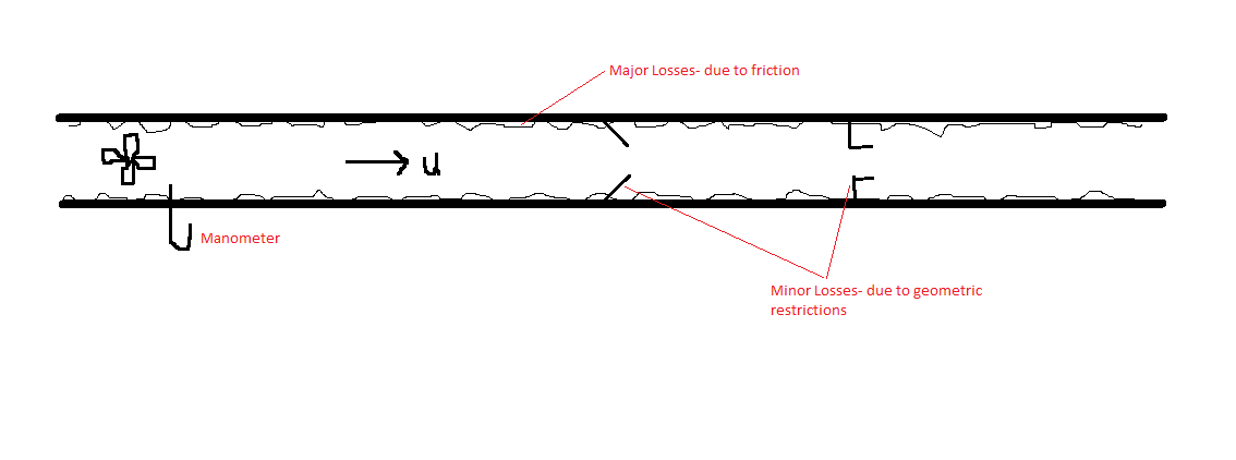
Diagram

(Forgive the pitiful diagram!)

Perhaps a more intuitive way to envision your question: If you wanted to determine losses in a given section of duct, you could place two manometers at chosen locations. Solving for $P_{manometer}$ at both manometers, you can calculate $\Delta P$ between manometers, again, the sum of Major and Minor losses in that section.

$\endgroup$
1
$\begingroup$

The 2 Primary Causes of Reduced Air Flow in Ducts

Friction

The first cause of reduced air flow is friction. When air moving through a duct rubs against the inner surfaces of that duct, it loses energy. It slows down. Its pressure drops. The more it rubs, the more those things happen. It's like walking down a busy sidewalk with your shoulder rubbing against the buildings.

The amount of friction depends on the nature of the material the duct is made of, how it was installed, how dirty it is, and how fast the air is moving. The photo above shows flex duct that's not pulled tight at all. Even though you can't see it all that well, you can tell that there's probably going to be a lot of rubbing when air moves through that duct. The same flex duct pulled tight is shown below. It still looks a bit rough but is much better than the one above. A piece of rigid metal duct would provide a much smoother surface.

Turbulence

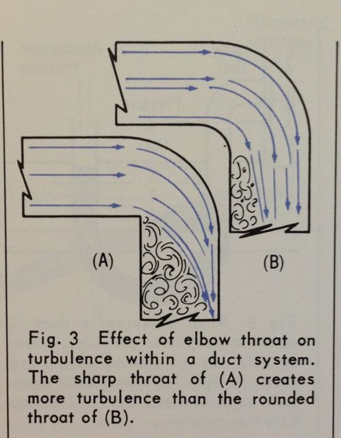
The other primary cause of reduced air flow is turbulence. This one is a kind of friction of the air rubbing against itself. The main cause of turbulence within ducts is turning the air. When you send air through a 90° turn, the type of fitting you use to do so can make a big difference.

The diagram below is from ACCA's booklet Understanding the Friction Chart. In both of the 90° elbows, the air enters nice and smoothly. That's laminar flow. When it makes the turn, however, notice that the air in the elbow with the curved inside edge (the throat) results in less turbulence. The elbow with the square throat produces more turbulence. Pick your fittings carefully!

enter image description here

$\endgroup$
1
  • $\begingroup$ "When air moving through a duct rubs against the inner surfaces of that duct, it loses energy." It's not only friction against the surfaces of the duct. Even in turbulent flow layers of fluid slide over each other, with friction between them, see shear viscosity. You also mention a photo but there isn't one shown. $\endgroup$
    – Gert
    Commented Oct 25, 2015 at 1:07

Your Answer

By clicking “Post Your Answer”, you agree to our terms of service and acknowledge you have read our privacy policy.

Not the answer you're looking for? Browse other questions tagged or ask your own question.