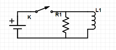
The title is a simplified form of my question. To be precise, I'm talking about the following circuit:

The inductor has a resistanse equal to the resistor in the circuit.
So, the question is that, as we close the circuit, how will the resistor's current-time graph look like? I talked with a few classmates of mine. Some of them believed that the current will raise up slowly, whereas I bet on a simple, quick change in current, from 0 to a constant value, as there's nothing connected parallel with the resistor. Then I made a digital square wave generator by a microprocessor (actually an Arduino), and using an old analog oscilloscope that we have in school, we tried to see the current-time graph of the resistor.
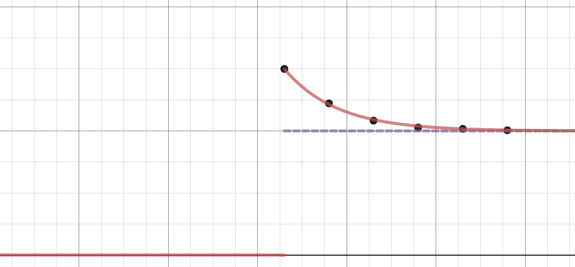
None of us had predicted what we saw on oscilloscope:

The purple dashed line is my prediction, the black points are measurement, and the red line is a model based on measurement.
However, I can't understand why this happens. There is a resistor connected to leads of a battery. So it has to run with the battery voltage (which is constant), thus with a constant current. In other hand, the inductor generates a voltage as well, so the voltage across resistor would be something else. To me it looks like a paradox, and surely it comes from my incomplete (maybe wrong?) knowledge in this field. So I'd be thankful if anyone here told me why I have problems with this circuit.
-By the way, I have also asked a teacher about this phenomenon, but his answer couldn't convince me: He said that since at first current can't go through the inductor (due to self inductance), so it goes through the resistor instead! After a short time it can flow in both components therefore less current goes through the resistor. I can't accept this, for example, you take a fixed resistor parallel with a variable resistor. If you change the value of the variable, the current trough the fixed resistor won't change.
