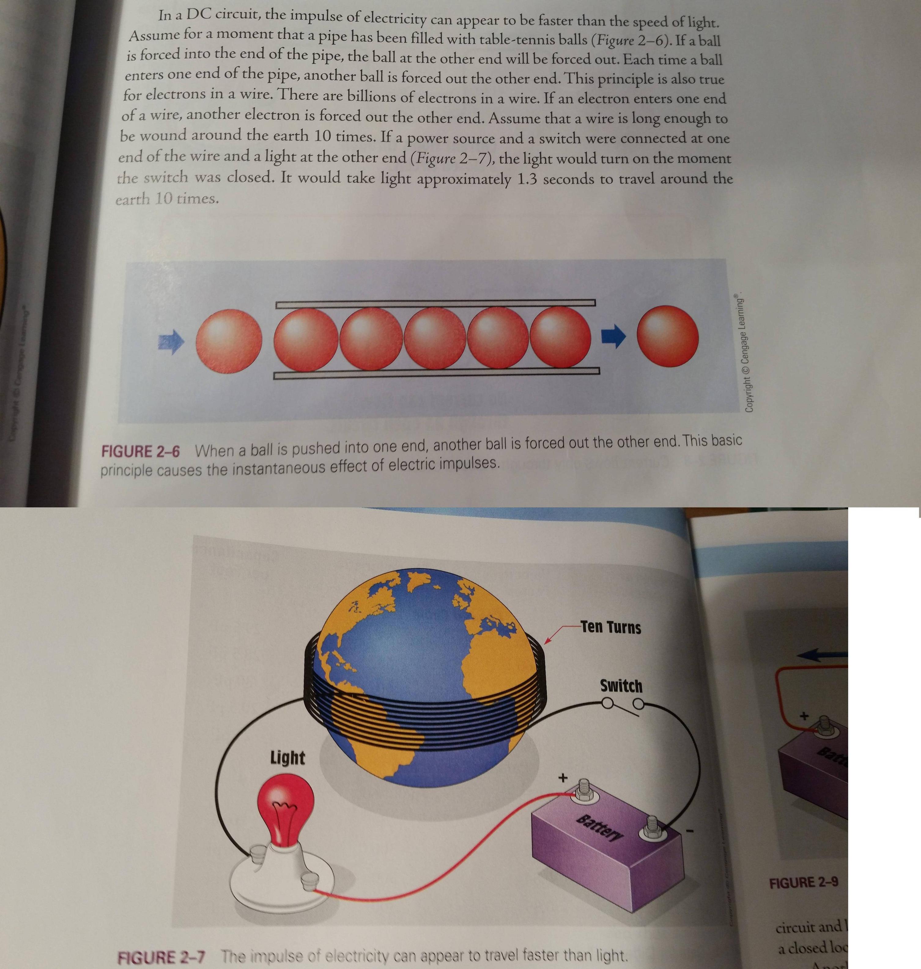
Let's think about the circuit you drew. It contains a battery, switch, bulb, and a very large inductor. In fact, the inductance of a wire that goes 10 times around the Earth can be calculated (I am going to assume an air core - in fact there is a piece of iron in the middle of the Earth which makes the resulting inductance greater).
$$L\approx N^2 R \mu_0 \mu_r \left(\log\left(\frac{8R}{a}\right)-2\right)$$
For a wire with 1 mm diameter, I calculate about 18 kH (kilo Henry) inductance for an air core - more because of the iron core but I don't know how much.
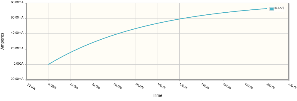
Now let's assume we have a 12 V battery and an 1.0 W light bulb - corresponding to a resistance of 144 Ohm. For a circuit with an inductor and a resistor in series, when you turn on the circuit it responds with a very slow time constant $\tau = \frac{L}{R} \approx 100 s$. A simple circuit simulation shows the current does indeed increase very gradually:

In a situation like this, you really have to think about the real physics - the "parasitics" in the circuit are not parasitic, they are essential to understand the behavior.
With that said - the location of the switch does not matter.
UPDATE a couple of comments said: "what if you arranged the wire so the inductance would be zero?". There is a way to almost do that: it is called "bifilar winding", where a wire is first wound one way, and then the other. in its simplest form, it would be a wire that is folded onto itself - it could be wound or straight, but because the "out" current and the "return" current are right next to each other, the magnetic field far away decreases very rapidly (dipole field) and it will be confined to the (small) region between the wires. This is in fact the principle of the transmission line.
If you use a transmission line, then it will indeed look "magically" that the electricity is traveling faster than the speed of light. Let me explain with a little diagram.

You see a battery, a lamp, a switch, and a long wire that returns on itself. This wire is a "shorted transmission line". Transmission lines have a "characteristic impedance" given by the capacitance and resistance per unit length,
$$Z = \sqrt\frac{L}{C}$$
Now even ordinary wire has a certain capacitance per unit length because the outgoing wire and its return are close together, and it also has a certain inductance because of the finite diameter of the wire. If you put the wires closer together the inductance goes down and the capacitance goes up, so the characteristic impedance goes down.
Key about transmission lines is that they "look just like a resistor" until the input voltage reaches the other end, and is reflected. So if you have a $3\cdot 10^8\;\rm{m}$ cable with a characteristic impedance of 50 Ohm and short circuited at the end, then it will look like a 50 Ohm resistor until the signal travels all the way to the short circuit (1 second) and the information "there is a short circuit" travels all the way back again (another second).
For such a transmission line, the light would turn on immediately - but not at full brightness: it would glow as though there was a 50 Ohm resistor in series. After a full two seconds (incidentally, the time it would take light to travel all the way to the end of the wire and back down the other leg), the bulb would become fully bright as the wire would now look like a short circuit.
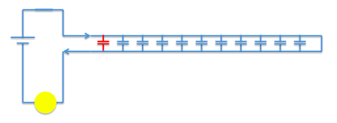
The whole analysis is a little bit more complex, but I hope you get the idea. Note that different geometries of wire will give different behavior, and that the speed of propagation of a signal through a transmission line is not always the speed of light: that depends on the characteristics of the medium between the wires. So analyzing a particular situation properly will be quite tricky. At any rate, the capacitance between the wires plays a very significant role in determining how things behave. You can think of the situation right after you turn on the switch as follows:

The red capacitor is "in series" with the circuit the moment the switch is closed, and briefly supplies the current to keep the lamp lit; a short moment later, the next capacitor "sees" the circuit and provides a current path, then the next one, etc.
You can Google "Telegrapher's equations" to learn much more about this topic.


