10
$\begingroup$

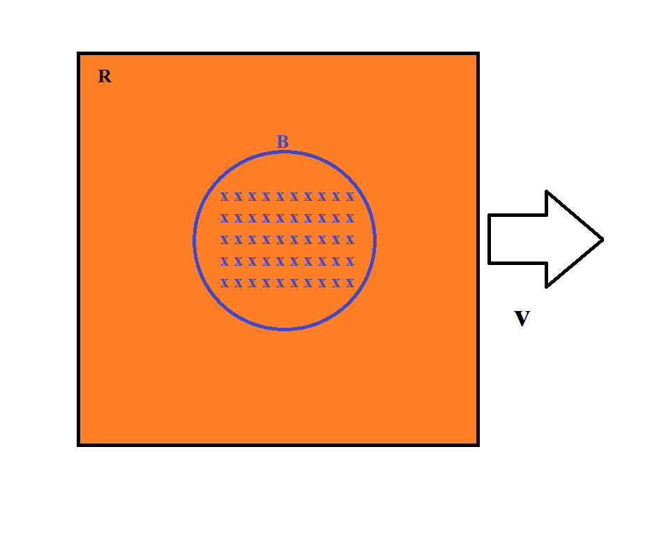
I have a conductor with volume $V$, passing a magnetic field($B$) with velocity($v$): enter image description here

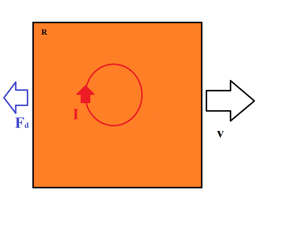
I'm trying to calculate the Eddy currents to figure out the magnitude of the drag force($F_d$) generated the Eddy's, how can that be done?

enter image description here

I could not find a direct formula, I noticed from a lot of sources that it seems to be a difficult task.

The conductor is in an open circuit(I don't think it makes a difference if it was in a closed circuit). Please let me know of any additional information I'm missing(not sure of all the required variables). I'll add them as an edit.

$\endgroup$
3
  • $\begingroup$ The magnetic field isn't changing right? $\endgroup$
    – Gaurav
    Commented Jul 22, 2015 at 12:28
  • $\begingroup$ Yes, the magnetic field is constant. The Eddy currents are induced due to the change in (A) over time(t). $\endgroup$
    – Pupil
    Commented Jul 22, 2015 at 19:08
  • $\begingroup$ You cannot have a definite boundary to the region where magnetic field exists because fringing is always there. You need to give us a physically meaningful experimental setup by which the magnetic field can be achieved so that we can proceed. $\endgroup$
    – Gaurav
    Commented Jul 24, 2015 at 8:15

5 Answers 5

6
+150
$\begingroup$

It's a complicated subject - but very well studied in the context of eddy current brakes, where the retarding force is used to create a braking force without mechanical friction / wear. For me, the starting point for finding out more was this post - in particular the posting by Jim Hardy contained lots of good links.

It seems that some of the most significant analyses were done by Smythe (1942), Schiber (1974) and Wouterse (1992) - see this thesis chapter for lots of detail.

Just summarizing, it seems there are four significant factors (surprise). These are

  1. The magnetic field itself: you expect the force to scale with the square of the field since the current induced scales with the field, and the force scales with the product of field and current.
  2. The velocity of the motion: the faster you move, the greater the change in flux and thus the greater the force. To first order you expect a linear relationship, although there is an indirect effect on resistance:
  3. The effective resistance of the plate (resistance per unit area). For non-ferromagnetic materials, the skin effect is not very large and current will flow through the body of the plate: but with ferromagnetic materials and high velocities, the current will only occur in the surface. This increases the resistance, and lowers the current and therefore the force
  4. The size of the magnetic patch: the larger the patch, the greater the line segment of current on which the magnetic force can act.

This means that for low speed, the force is expressed as

$$F = \frac{v\cdot B^2\cdot A}{\rho/t}$$

where $v$ is the velocity, $B$ the magnetic field, $A$ the area of the magnetic patch, $\rho$ the volume resistivity and $t$ the thickness of the plate (area resistivity $\sigma = \rho / t$). Note that I modified the equation given in the reference slightly - it was showing the torque for a rotating disk, from which I deduced the force ($F = \frac{\Gamma}{R}$)

Now when the speed becomes higher, the induced currents can generate a field that is a significant fraction of the applied field; and as I mentioned, the skin effect can start to play. Both of these will generate additional term in the relationship between force and velocity, but at this point the calculations become tricky to do analytically and are typically done by fitting experimental data.

But the above should give us a start. It tells us that thicker conductors experience greater force, and that as things move faster, the force will increase. There is a lovely experiment demonstrating eddy currents in which a strong magnet is dropped down a thick copper tube, and appears almost to float: this observation is entirely consistent with the above equation (you need thick copper to get sufficient induction; and since the force increases with velocity there will be a velocity at which the retarding force cancels gravity).

A video showing this phenomenon is shown here - incidentally it shows that the effect is stronger for the copper tube than for the aluminum tube, as is consistent with the fact that the volume conductivity of copper is greater than that of aluminum (by about 1.5x).
$\endgroup$
13
  • 1
    $\begingroup$ Have you ever tried moving a piece of nonmagnetic metal in the vicinity of a strong magnet? I have - in the fringe field of a MRI machine, a block of aluminum just doesn't want to be moved. See for example this video The velocity is much lower than 1 m/s and the block just doesn't want to fall... And remember, eddy current brakes really do work. $\endgroup$
    – Floris
    Commented Jul 27, 2015 at 17:29
  • 1
    $\begingroup$ Not sure what you mean by "closed loop" - the copper is locally a closed loop already. Anything that affects the factors in the equation will help. In particular grooves / laminations reduce the apparent area over which a current can develop. The usual terminology is "groove" when the copper is still in on piece with slots in it, and "laminated " when there are multiple pieces held (glued) together, with insulation in between (eg varnish etc) $\endgroup$
    – Floris
    Commented Jul 28, 2015 at 17:38
  • 1
    $\begingroup$ @Key the equations get significantly messier - see equation 3.5 in the thesis chapter that I linked in the answer and the explanation of its derivation. $\endgroup$
    – Floris
    Commented Jul 29, 2015 at 5:27
  • 1
    $\begingroup$ @Key Nice answer and references. I just want to note that I derived the same answer for the force law in my answer below ($\sigma$ is $\rho^{-1}$, $V$ is $At$). $\endgroup$
    – octonion
    Commented Jul 29, 2015 at 19:28
  • 1
    $\begingroup$ The force decreases when the currents induce so much "counter" field that there is not much field left to act on these currents. So yes the relationship does flatten off as velocity goes up. And it is not intuitively obvious. $\endgroup$
    – Floris
    Commented Jul 30, 2015 at 1:24
3
$\begingroup$

I can give a back-of-the-envelope derivation of a drag force that ignores fringe effects and other complications. Say the conductor is a plate of thickness $\Delta z$ traveling with velocity $v$ in the x direction. Take the magnetic field to be constant in a rectangular area, with the the $\Delta y$ side perpendicular to the velocity much longer than $\Delta x$ side.

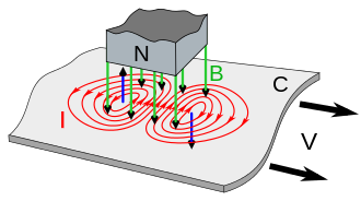
The induced electric field will circulate around the leading and trailing edges of the rectangle in opposite directions. See the image from Wikipedia, and notice how the current (proportional to the field) is stronger in the middle and is pointing perpendicular to the velocity.

enter image description here

As the $\Delta y$ length of the rectangle becomes longer only the y directed field in the middle is significant (just like a long solenoid).

Then taking a rectangular integration path of length L in the y direction and using $$\oint E\cdot dl = E L$$ $$ = -d\Phi / dt = -B dA/dt = -B v L, $$ so the magnitude of E $$ E = B v, $$ and it is approximately zero outside of the volume $V = \Delta x \Delta y \Delta z$.

Then by Ohm's law the power lost is $$ P = \int E \cdot J dV = \int \sigma \lvert E\rvert^2 dV = \sigma B^2 v^2 V, $$ where $\sigma$ is the conductivity of the material. If you exert a force $F_d$ so as to maintain the velocity $v$ you are doing work per time $F_d v$, so the force must be $$ F_d = \sigma B^2 v V. $$

In general I'd imagine there would be a coefficient out front which depends on more detailed geometry. For comparison there is a power dissipation formula here with some different numerical factors out front and using frequency instead of velocity, but the same form.

Now if you are looking to do calculate a more realistic set of eddy currents, take $B(x-vt,y,z)$ to be the magnetic field. Then $$\nabla \times E = -\partial_t B = v\,\partial_x B $$ and so since $\nabla\cdot E =0,$ from the usual formula for inverting the curl, $$E(\mathbf{r}) = \nabla\times \int \frac {v\,\partial_x B(\mathbf{r^\prime})}{4\pi \lvert\mathbf{r}-\mathbf{r^\prime}\rvert}dV^\prime.$$

Then you can integrate $\sigma \lvert E\rvert^2$ find the power dissipated and then the force as above.

$\endgroup$
1
$\begingroup$

The eddy currents are caused when the metal plate which is subjected to a magnetic field is take out rapidly. This causes current to flow within the metal plate and thus opposing the already existing magnetic field (Lenz's law).

To calculate the current I think the approach would be as follows.

We have

  • $F_d$, external force
  • $B$, magnetic field (external)
  • $R_d$, radius of the area under the magnetic field
  • $V$, potential difference between the two ends of the magnetic field
  • $R$, resistance of the external loop of the metal disk (I am not going into the calculations)

So now $$\int_{\partial \Sigma} \vec{E} \cdot d \vec{l} = - \frac{d}{dt}\int_\Sigma \vec{B} \cdot d \vec{A} \, .$$ So $$V = B \cdot \text{change in area with time} \, .$$ The change of are with time is $(\pi R_d / 2) (F_d/M)$ where $M$ is the mass of the whole body.

To make things simple lets say that the body is moving at a constant velocity, i.e. $F_d$ is just so that it overcomes the resisting force keeping the body moving at velocity $u$.

Then $V = B (\pi R_d / 2) * u$. Now the current through the block would be $I = V / R$ where $R$ is resistance.

$\endgroup$
1
  • 1
    $\begingroup$ Welcome to Physics Stack Exchange. Please note that this site supports TeX style math. I fixed up the math in the answer to use it. Please click the edit button so you can see how I did it. Also please do not post pictures of equations; type them in. This avoids link rot and makes it easier for people to edit the post if there are mistakes etc. Finally, there were a lot of grammar and punctuation errors in the answer, so I fixed them. If English is not your first language don't worry too much about the grammar, but please do at least capitalize "I" and use proper punctuation. $\endgroup$
    – DanielSank
    Commented Jul 23, 2015 at 23:19
1
$\begingroup$

I don't have the expertise you're looking for, but here's a crack at it:

This is a really hard problem whose answer depends on the material properties. In particular, the answer depends on how big the 'eddies' are: if the current moves in roughly a big circle then the effect is large, but if there are lots of little eddies the effect is small.

However, there's a standard high-school physics experiment where sending a plate of metal through a magnetic field significantly slows it down (because of the large eddy currents), but sending the same plate of metal with lots of little notches cut out reduces the effect.

The fact that cutting notches out of the plate can have an effect at all means that typically the eddies are large, on the order of the size of the plate. That means that DanielSank's answer should be roughly, order-of-magnitude correct.

$\endgroup$
1
  • $\begingroup$ That is true, and the base of all this. However, one of my major concerns is with the importance of the material's resistance. I think based of what you said about the groove design, it doesn't matter as much as the magnitude of Eddy's. $\endgroup$
    – Pupil
    Commented Jul 25, 2015 at 17:38
1
$\begingroup$

I think some of the earlier answers have covered a lot of the math but to make sure you see how complex it is to calculate it, remember that as the distance from the conductor increases the flux density decreases - nonlinearly. Frequently it is approximated by the inverse square rule but that is only for a specific geometry. It is definitely not close to an inverse square law for a lot of magnet geometries such as thin magnets. For example we just did the measurements on a 1 inch square x 0.5 inch thick N50 neodymium magnet and at the surface it measures 4,800 gauss but at 0.25 inches it is 2,500 gauss and at 0.5 inches it is 1,200. For the inverse square law it should have been 1/4 not 1/2. Furthermore, on a permanent magnet, the flux varies dramatically over the surface and the angle of the flux varies dramatically. For a 1 inch square x 2 mm thick neo N40 magnet, it can measure 1,000 gauss in the center and 2,300 gauss on the corners. When you look at the angle of the flux on the edges where it is the strongest, they are nearly parallel to the surface whereas the vectors in the center will be perpendicular. As magnet thickness increases this effect is decreased and a 1 inch cube will have a more uniform profile across the surface.

It is easy to write the equation that says to integrate the total flux in the volumetric space above the magnet and its interaction with the entire volume of the conducting material, but it is quite difficult to do this and account for the variations.

To complicate the matter even more, as your velocity increases the induced eddy currents increase and as the magnetic flux increases in the conducting material it will require greater work to induce the next amount of flux because the resistance is increasing in the material.

Even though this will still not cover everything as the flux is moving away from the surface of the magnet it is changing in flux density and angle so that as you move into thicker materials such as aluminum or copper each increment of thickness produces fewer eddy currents. For example, going from 0.25 inch thick copper to 0.5 inch thick copper will definitely increase the drag but nowhere near doubling the force. It will depend on the magnet. For a 2 inch N52 cube magnet increasing from 0.25 inch thick to 0.5 inch thick will probably increase the drag around 80% but taking a 1 inch square x 0.25 inch thick N50 magnet it may only get a 40-50% increase in drag effect.

Now, while calculating it can be extremely tedious even if you have some of the better magnetic modeling software packages you will find that building a model and measuring the force will be much easier. That way you can use exactly what you want in your own application and see what results you get. At SuperMagnetMan, that is what we recommend for most people because they can easily understand the results they get from a test but they will not know the limits of the software and if it accounted for everything. We get magnet designs modeled all the time for our customers and they are usually close to correct but never have they been dead on. I always try to build a scale model of what we need and send in real data to the modeler so they can see how close the model is to reality. Then they can adjust parameters until the model matches reality and then scale up the model and the data is usually pretty accurate with that approach.

$\endgroup$

Your Answer

By clicking “Post Your Answer”, you agree to our terms of service and acknowledge you have read our privacy policy.

Not the answer you're looking for? Browse other questions tagged or ask your own question.