1
$\begingroup$

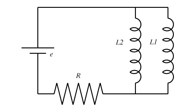
I'm having trouble with visualizing the following problem, which is asking me for the final, steady current in both inductors $L_{1}$ and $L_{2}$. I was thinking that after a long time, essentially the current will be stable and thus there will be no induced current in the inductors. However, how would the current in the circuit split in this case? (I suppose that we would have two short wires as the resistance of the inductors is 0). I know that the current through the resistor is:

$I_{R} = \displaystyle\frac{e}{R}$

However, I really can't visualize how short circuits work, and mostly in this case in which we have two paths with zero resistance. How would the currents split?

Here is a picture of the problem. enter image description here
$\endgroup$
1
  • $\begingroup$ Have you tried looking at the ratio of the inductor currents for any (finite) time $t$? $\endgroup$ Commented Mar 17, 2014 at 21:58

3 Answers 3

1
$\begingroup$

$\def\ddt{\frac{d}{dt}}\def\l\{\left}\def\r{\right}\def\rmS{S}$The network is over-idealized. Any inductor currents $i_1$, $i_2$ with $i_1+i_2 = \frac{e}{R}$ are possible at steady state.

If you are given initial currents $i_1(0),i_2(0)$ then current over time results with $i_\rmS:=i_1+i_2$ from \begin{align} \ddt i_1(t) &= \frac1{L_1}\l(e - R\cdot i_\rmS(t)\r)\\ \ddt i_2(t) &= \frac1{L_2}\l(e - R\cdot i_\rmS(t)\r) \end{align} Adding the equations gives \begin{align} \ddt i_\rmS (t) = \l(\frac1{L_1}+\frac1{L_2}\r)\l(e - R\cdot i_\rmS\r). \end{align} Now you can determine the sum current $i_\rmS(t)$ over time with the initial condition $i_\rmS(0)=i_1(0)+i_2(0)$. From that you can determine $e-R\cdot i_\rmS$ and therefore $i_1(t)$ and $i_2(t)$. The limit $t\rightarrow\infty$ gives you the steady state values.

The situation changes if the inductors have internal resistance (which is not indicated in the circuit diagram). Then you can calculate the steady-state currents with the inductors replaced by the internal resistances.

$\endgroup$
0
$\begingroup$
I was thinking that after a long time, essentially the current will be stable and 
thus there will be no induced current in the inductors

When we use inductors, we deal with induced EMF and not induced current. The induced EMF works to reduce the net potential across the inductor altering the amount of current that flows from the battery but not any current they induce on their own.

In the stable state, inductors do no have induced EMF and theoretically act like resistance less wires. So here you can find the net current flowing through the circuit by using ohm's law across the only resistance left. This current would be equally distributed for the 2 inductors.

$\endgroup$
1
  • $\begingroup$ Equal distribution of the currents on the two inductors is one of many possible steady-states. If the inductors are ideal any constant loop current through the inductor loop can be superimposed. $\endgroup$
    – Tobias
    Commented Jun 4, 2014 at 12:02
-1
$\begingroup$

try taking a look at this page it goes in to good detail about inductors in a dc circuit.

http://www.ibiblio.org/kuphaldt/electricCircuits/DC/DC_15.html

$\endgroup$
1
  • $\begingroup$ Welcome to the site! We discourage link-only answers here, please provide a meaningful summary of the contents of that link. We try to build useful content, not a link farm. $\endgroup$ Commented Apr 4, 2014 at 0:02

Your Answer

By clicking “Post Your Answer”, you agree to our terms of service and acknowledge you have read our privacy policy.

Not the answer you're looking for? Browse other questions tagged or ask your own question.