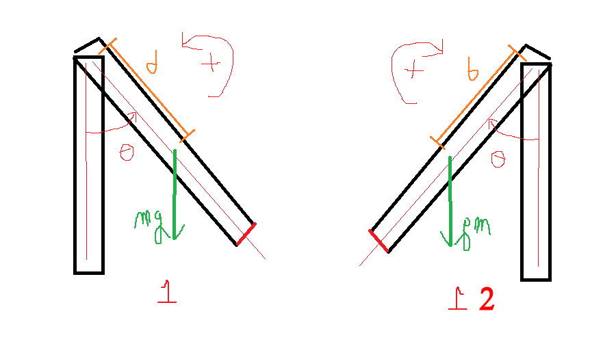
In your figure 1 let's define an angle unit vector $\hat \theta_{\rm a}$ in the anticlockwise direction.
So the angle as drawn is $\theta \hat \theta_{\rm a}$, the angular velocity is $\dot \theta \hat \theta_{\rm a}$ and the angular acceleration is $\ddot \theta \hat \theta_{\rm a}$.
The torque is $mgd \sin \theta \, (-\hat \theta_{\rm a}) = - mgd \sin \theta \, \hat \theta_{\rm a} $ and from that you get your equation $$I\ddot \theta \hat \theta_{\rm a} =- mgd \sin \theta \, \hat \theta_{\rm a} \Rightarrow \ddot \theta =- \dfrac{mgd \sin \theta}{I}$$
In your figure 2 let's define an angle unit vector $\hat \theta_{\rm c}$ in the clockwise direction.
So the angle as drawn is $\theta (-\hat \theta_{\rm c})=-\theta \hat \theta_{\rm c}$, the angular velocity is $\dot \theta (-\hat \theta_{\rm c})=-\dot\theta \hat \theta_{\rm c}$ and the angular acceleration is $\ddot \theta (-\hat \theta_{\rm c})= - \ddot \theta \hat \theta_{\rm c}$.
The torque is $mgd \sin \theta \, \hat \theta_{\rm c}$ and from that you get your equation $$-I\ddot \theta \hat \theta_{\rm c} =mgd \sin \theta \, \hat \theta_{\rm c} \Rightarrow \ddot \theta =- \dfrac{mgd \sin \theta}{I}$$
If your diagrams were showing the positions at maximum excursion at time equal to zero and the amplitude of the motion was $\Theta$ then for figure 1 the initial angular displacement is $\Theta \hat \theta_{\rm a}$ and that for figure 2 is $\Theta (-\hat \theta_{\rm c})= -\Theta \hat \theta_{\rm c}$
You would made life easier by usng the mirror image of figure 1 when drawing figure 2 which is the same as looking at the figure 1 pendulum from the other side ie looking at figure 1 from "inside" the computer screen.

