added 904 characters in body
Source Link
Farcher
  • 99.9k
  • 5
  • 83
  • 215

In your figure 1 let's defineI have rewritten my answer to address the concerns made in comments by @juancarlosvegaoliver.

Instead of it being a unit vectorrotation let it be simple harmonic motion in one dimension along the $\hat k$$x$-axis (vales increasing from left to represent an anticlockwise rotationright) and then I will show its relevance to the question asked.

So the angle as drawnenter image description here

The displacement from $O$ is $\theta \hat k$,$\vec x = x \hat x$ where $x$ is the angularcomponent of the displacement in the direction of $\hat x$.
The velocity is $\dot \theta \hat k$$\dot x \hat x$ and the angular acceleration is $\ddot \theta \hat k$$\ddot x \hat x$.

The torque
The force is $mgd \sin \theta \, (-\hat k) = - mgd \sin \theta \, \hat k $$-k\vec x = -kx \hat x$ and from that you get your equation $$I\ddot \theta \hat k =- mgd \sin \theta \, \hat k \Rightarrow \ddot \theta =- \dfrac{mgd \sin \theta}{I}$$


In your figure$-kx$ is the 2component let's define a unit vectorof the force in the direction of $\hat K$ to represent a clockwise rotation$\hat x$.

SoAt a position like $A$ the angle as drawndisplacement $\vec x$ in the direction of $\hat x$ and the direction of the (restoring) force is in the direction of $\theta (-\hat K)=-\theta \hat K$,$-\hat x$.
At position $B$ the angular velocitydisplacement is in the direction of $\dot \theta (-\hat K)=-\dot\theta \hat K$$-\hat x$ and the angular accelerationdirection of the (restoring) force is in the direction of $\ddot \theta (-\hat K)= - \ddot \theta \hat K$$+\hat x$.

The torque isSo using $mgd \sin \theta \, \hat K$ and from that you get your equation$\vec F = m\vec a \Rightarrow -kx\hat x = m\ddot x \hat x \Rightarrow \ddot x = -\frac km x$ for all values of $$-I\ddot \theta \hat K =mgd \sin \theta \, \hat K \Rightarrow \ddot \theta =- \dfrac{mgd \sin \theta}{I}$$$x$ whether positive or negative.


If your diagrams were showingSwitching the positions at maximum excursion at time equaldirection of the unit vector to zero$\hat X = - \hat x$ makes no difference because now $\vec x = -x \hat X = -x \,(-\hat x) = x \hat x$ and $\vec a = -\ddot x \hat X = -\ddot x \,(-\hat x) = \ddot x \hat x$.
$\vec F = +kx\hat X = +kx (-\hat x) = -kx \hat x$.
For example, $2 \hat X = -2 \hat x$ and both give the amplitude ofposition as $x=-2$

Having the motion was $\Theta$ then$x$ axis pointing from right to left only results in a change of sign so, for figureexample a position of $x=-2$ would now be $x=+2$.


Diagram 1 is the initial angular displacementsame as my diagram except that now $\vec x = x\hat x$ etc is replaced by $\Theta \hat k$$\theta \hat k$ etc and that for figure 2$\vec F - -k x \hat x$ is replaced by $\Theta (-\hat K)= -\Theta \hat K$ which$\vec \tau = - mgd \sin \theta \,\hat k$.
The direction of $x$ increasing is consistent withto the fact thatright is replaced by the direction of $\hat k = -\hat K$$\theta$ increasing is anticlockwise.


You would made life easier by usng the mirror image of figure 1 when drawing figureDiagram 2 which is just a reversal of the same as looking atunit vector such that the figurenew unit vector 1 pendulum from$\hat K = - \hat k$ with the other side ie looking at figuredirection of increasing 1 from "inside"$\theta$ still anticlockwise.
I have shown for the computer screenone dimension motion reversing the direction of the unit vector does not change anything and it is the same for the example with rotation.
enter image description here
$\vec \theta = -\theta \hat K = -\theta \,(-\hat k) = \theta \hat k$ and $\vec \alpha = -\ddot \theta \hat K = -\ddot \theta \,(-\hat k) = \ddot \theta \hat k$.
$\vec \tau = +mgd\hat K = +mgd (-\hat k) = -mgd \hat k$.

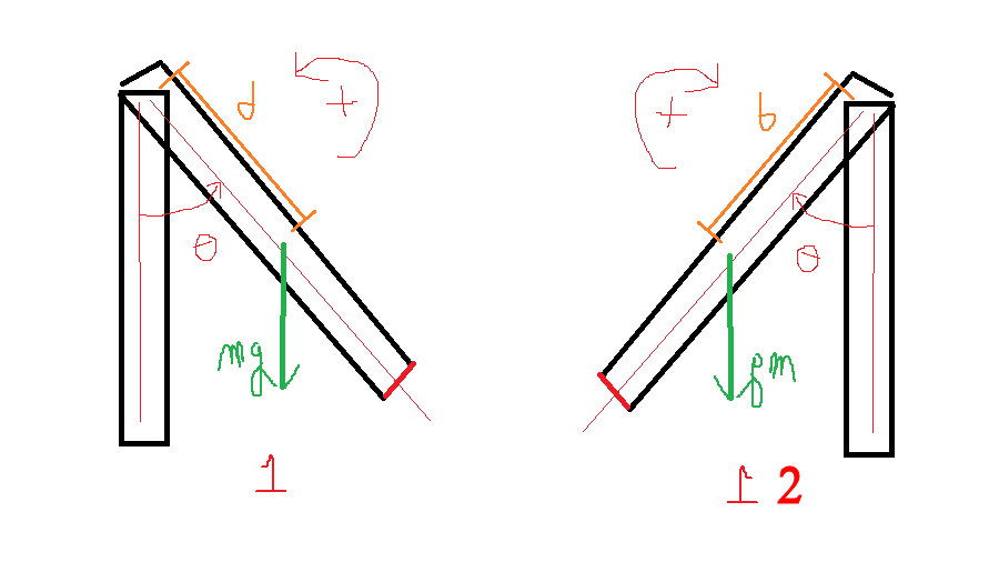
In your figure 1 let's define a unit vector $\hat k$ to represent an anticlockwise rotation.

So the angle as drawn is $\theta \hat k$, the angular velocity is $\dot \theta \hat k$ and the angular acceleration is $\ddot \theta \hat k$.

The torque is $mgd \sin \theta \, (-\hat k) = - mgd \sin \theta \, \hat k $ and from that you get your equation $$I\ddot \theta \hat k =- mgd \sin \theta \, \hat k \Rightarrow \ddot \theta =- \dfrac{mgd \sin \theta}{I}$$


In your figure 2 let's define a unit vector $\hat K$ to represent a clockwise rotation.

So the angle as drawn is $\theta (-\hat K)=-\theta \hat K$, the angular velocity is $\dot \theta (-\hat K)=-\dot\theta \hat K$ and the angular acceleration is $\ddot \theta (-\hat K)= - \ddot \theta \hat K$.

The torque is $mgd \sin \theta \, \hat K$ and from that you get your equation $$-I\ddot \theta \hat K =mgd \sin \theta \, \hat K \Rightarrow \ddot \theta =- \dfrac{mgd \sin \theta}{I}$$


If your diagrams were showing the positions at maximum excursion at time equal to zero and the amplitude of the motion was $\Theta$ then for figure 1 the initial angular displacement is $\Theta \hat k$ and that for figure 2 is $\Theta (-\hat K)= -\Theta \hat K$ which is consistent with the fact that $\hat k = -\hat K$.


You would made life easier by usng the mirror image of figure 1 when drawing figure 2 which is the same as looking at the figure 1 pendulum from the other side ie looking at figure 1 from "inside" the computer screen.

enter image description here

I have rewritten my answer to address the concerns made in comments by @juancarlosvegaoliver.

Instead of it being a rotation let it be simple harmonic motion in one dimension along the $x$-axis (vales increasing from left to right) and then I will show its relevance to the question asked.

enter image description here

The displacement from $O$ is $\vec x = x \hat x$ where $x$ is the component of the displacement in the direction of $\hat x$.
The velocity is $\dot x \hat x$ and the acceleration is $\ddot x \hat x$.
The force is $-k\vec x = -kx \hat x$ and $-kx$ is the component of the force in the direction of $\hat x$.

At a position like $A$ the displacement $\vec x$ in the direction of $\hat x$ and the direction of the (restoring) force is in the direction of $-\hat x$.
At position $B$ the displacement is in the direction of $-\hat x$ and the direction of the (restoring) force is in the direction of $+\hat x$.

So using $\vec F = m\vec a \Rightarrow -kx\hat x = m\ddot x \hat x \Rightarrow \ddot x = -\frac km x$ for all values of $x$ whether positive or negative.

Switching the direction of the unit vector to $\hat X = - \hat x$ makes no difference because now $\vec x = -x \hat X = -x \,(-\hat x) = x \hat x$ and $\vec a = -\ddot x \hat X = -\ddot x \,(-\hat x) = \ddot x \hat x$.
$\vec F = +kx\hat X = +kx (-\hat x) = -kx \hat x$.
For example, $2 \hat X = -2 \hat x$ and both give the position as $x=-2$

Having the $x$ axis pointing from right to left only results in a change of sign so, for example a position of $x=-2$ would now be $x=+2$.


Diagram 1 is the same as my diagram except that now $\vec x = x\hat x$ etc is replaced by $\theta \hat k$ etc and $\vec F - -k x \hat x$ is replaced by $\vec \tau = - mgd \sin \theta \,\hat k$.
The direction of $x$ increasing is to the right is replaced by the direction of $\theta$ increasing is anticlockwise.

Diagram 2 is just a reversal of the unit vector such that the new unit vector $\hat K = - \hat k$ with the direction of increasing $\theta$ still anticlockwise.
I have shown for the one dimension motion reversing the direction of the unit vector does not change anything and it is the same for the example with rotation.
$\vec \theta = -\theta \hat K = -\theta \,(-\hat k) = \theta \hat k$ and $\vec \alpha = -\ddot \theta \hat K = -\ddot \theta \,(-\hat k) = \ddot \theta \hat k$.
$\vec \tau = +mgd\hat K = +mgd (-\hat k) = -mgd \hat k$.

deleted 212 characters in body
Source Link
Farcher
  • 99.9k
  • 5
  • 83
  • 215

In your figure 1 let's define an anglea unit vector $\hat \theta_{\rm a}$ in the$\hat k$ to represent an anticlockwise directionrotation.

So the angle as drawn is $\theta \hat \theta_{\rm a}$$\theta \hat k$, the angular velocity is $\dot \theta \hat \theta_{\rm a}$$\dot \theta \hat k$ and the angular acceleration is $\ddot \theta \hat \theta_{\rm a}$$\ddot \theta \hat k$.

The torque is $mgd \sin \theta \, (-\hat \theta_{\rm a}) = - mgd \sin \theta \, \hat \theta_{\rm a} $$mgd \sin \theta \, (-\hat k) = - mgd \sin \theta \, \hat k $ and from that you get your equation $$I\ddot \theta \hat \theta_{\rm a} =- mgd \sin \theta \, \hat \theta_{\rm a} \Rightarrow \ddot \theta =- \dfrac{mgd \sin \theta}{I}$$$$I\ddot \theta \hat k =- mgd \sin \theta \, \hat k \Rightarrow \ddot \theta =- \dfrac{mgd \sin \theta}{I}$$


In your figure 2 let's define an anglea unit vector $\hat \theta_{\rm c}$ in the$\hat K$ to represent a clockwise directionrotation.

So the angle as drawn is $\theta (-\hat \theta_{\rm c})=-\theta \hat \theta_{\rm c}$$\theta (-\hat K)=-\theta \hat K$, the angular velocity is $\dot \theta (-\hat \theta_{\rm c})=-\dot\theta \hat \theta_{\rm c}$$\dot \theta (-\hat K)=-\dot\theta \hat K$ and the angular acceleration is $\ddot \theta (-\hat \theta_{\rm c})= - \ddot \theta \hat \theta_{\rm c}$$\ddot \theta (-\hat K)= - \ddot \theta \hat K$.

The torque is $mgd \sin \theta \, \hat \theta_{\rm c}$$mgd \sin \theta \, \hat K$ and from that you get your equation $$-I\ddot \theta \hat \theta_{\rm c} =mgd \sin \theta \, \hat \theta_{\rm c} \Rightarrow \ddot \theta =- \dfrac{mgd \sin \theta}{I}$$$$-I\ddot \theta \hat K =mgd \sin \theta \, \hat K \Rightarrow \ddot \theta =- \dfrac{mgd \sin \theta}{I}$$


If your diagrams were showing the positions at maximum excursion at time equal to zero and the amplitude of the motion was $\Theta$ then for figure 1 the initial angular displacement is $\Theta \hat \theta_{\rm a}$$\Theta \hat k$ and that for figure 2 is $\Theta (-\hat \theta_{\rm c})= -\Theta \hat \theta_{\rm c}$$\Theta (-\hat K)= -\Theta \hat K$ which is consistent with the fact that $\hat k = -\hat K$.


You would made life easier by usng the mirror image of figure 1 when drawing figure 2 which is the same as looking at the figure 1 pendulum from the other side ie looking at figure 1 from "inside" the computer screen.

enter image description here

In your figure 1 let's define an angle unit vector $\hat \theta_{\rm a}$ in the anticlockwise direction.

So the angle as drawn is $\theta \hat \theta_{\rm a}$, the angular velocity is $\dot \theta \hat \theta_{\rm a}$ and the angular acceleration is $\ddot \theta \hat \theta_{\rm a}$.

The torque is $mgd \sin \theta \, (-\hat \theta_{\rm a}) = - mgd \sin \theta \, \hat \theta_{\rm a} $ and from that you get your equation $$I\ddot \theta \hat \theta_{\rm a} =- mgd \sin \theta \, \hat \theta_{\rm a} \Rightarrow \ddot \theta =- \dfrac{mgd \sin \theta}{I}$$


In your figure 2 let's define an angle unit vector $\hat \theta_{\rm c}$ in the clockwise direction.

So the angle as drawn is $\theta (-\hat \theta_{\rm c})=-\theta \hat \theta_{\rm c}$, the angular velocity is $\dot \theta (-\hat \theta_{\rm c})=-\dot\theta \hat \theta_{\rm c}$ and the angular acceleration is $\ddot \theta (-\hat \theta_{\rm c})= - \ddot \theta \hat \theta_{\rm c}$.

The torque is $mgd \sin \theta \, \hat \theta_{\rm c}$ and from that you get your equation $$-I\ddot \theta \hat \theta_{\rm c} =mgd \sin \theta \, \hat \theta_{\rm c} \Rightarrow \ddot \theta =- \dfrac{mgd \sin \theta}{I}$$


If your diagrams were showing the positions at maximum excursion at time equal to zero and the amplitude of the motion was $\Theta$ then for figure 1 the initial angular displacement is $\Theta \hat \theta_{\rm a}$ and that for figure 2 is $\Theta (-\hat \theta_{\rm c})= -\Theta \hat \theta_{\rm c}$


You would made life easier by usng the mirror image of figure 1 when drawing figure 2 which is the same as looking at the figure 1 pendulum from the other side ie looking at figure 1 from "inside" the computer screen.

enter image description here

In your figure 1 let's define a unit vector $\hat k$ to represent an anticlockwise rotation.

So the angle as drawn is $\theta \hat k$, the angular velocity is $\dot \theta \hat k$ and the angular acceleration is $\ddot \theta \hat k$.

The torque is $mgd \sin \theta \, (-\hat k) = - mgd \sin \theta \, \hat k $ and from that you get your equation $$I\ddot \theta \hat k =- mgd \sin \theta \, \hat k \Rightarrow \ddot \theta =- \dfrac{mgd \sin \theta}{I}$$


In your figure 2 let's define a unit vector $\hat K$ to represent a clockwise rotation.

So the angle as drawn is $\theta (-\hat K)=-\theta \hat K$, the angular velocity is $\dot \theta (-\hat K)=-\dot\theta \hat K$ and the angular acceleration is $\ddot \theta (-\hat K)= - \ddot \theta \hat K$.

The torque is $mgd \sin \theta \, \hat K$ and from that you get your equation $$-I\ddot \theta \hat K =mgd \sin \theta \, \hat K \Rightarrow \ddot \theta =- \dfrac{mgd \sin \theta}{I}$$


If your diagrams were showing the positions at maximum excursion at time equal to zero and the amplitude of the motion was $\Theta$ then for figure 1 the initial angular displacement is $\Theta \hat k$ and that for figure 2 is $\Theta (-\hat K)= -\Theta \hat K$ which is consistent with the fact that $\hat k = -\hat K$.


You would made life easier by usng the mirror image of figure 1 when drawing figure 2 which is the same as looking at the figure 1 pendulum from the other side ie looking at figure 1 from "inside" the computer screen.

enter image description here

Source Link
Farcher
  • 99.9k
  • 5
  • 83
  • 215

In your figure 1 let's define an angle unit vector $\hat \theta_{\rm a}$ in the anticlockwise direction.

So the angle as drawn is $\theta \hat \theta_{\rm a}$, the angular velocity is $\dot \theta \hat \theta_{\rm a}$ and the angular acceleration is $\ddot \theta \hat \theta_{\rm a}$.

The torque is $mgd \sin \theta \, (-\hat \theta_{\rm a}) = - mgd \sin \theta \, \hat \theta_{\rm a} $ and from that you get your equation $$I\ddot \theta \hat \theta_{\rm a} =- mgd \sin \theta \, \hat \theta_{\rm a} \Rightarrow \ddot \theta =- \dfrac{mgd \sin \theta}{I}$$


In your figure 2 let's define an angle unit vector $\hat \theta_{\rm c}$ in the clockwise direction.

So the angle as drawn is $\theta (-\hat \theta_{\rm c})=-\theta \hat \theta_{\rm c}$, the angular velocity is $\dot \theta (-\hat \theta_{\rm c})=-\dot\theta \hat \theta_{\rm c}$ and the angular acceleration is $\ddot \theta (-\hat \theta_{\rm c})= - \ddot \theta \hat \theta_{\rm c}$.

The torque is $mgd \sin \theta \, \hat \theta_{\rm c}$ and from that you get your equation $$-I\ddot \theta \hat \theta_{\rm c} =mgd \sin \theta \, \hat \theta_{\rm c} \Rightarrow \ddot \theta =- \dfrac{mgd \sin \theta}{I}$$


If your diagrams were showing the positions at maximum excursion at time equal to zero and the amplitude of the motion was $\Theta$ then for figure 1 the initial angular displacement is $\Theta \hat \theta_{\rm a}$ and that for figure 2 is $\Theta (-\hat \theta_{\rm c})= -\Theta \hat \theta_{\rm c}$


You would made life easier by usng the mirror image of figure 1 when drawing figure 2 which is the same as looking at the figure 1 pendulum from the other side ie looking at figure 1 from "inside" the computer screen.

enter image description here