7
$\begingroup$

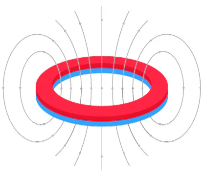
I always thought that the field of a short length axially magnetized ring magnet resembles this illustration here of Fig. 1 similar to the magnetic field of a single current loop:

Ring Magnet correct field

Fig.1 Axial Ring Magnet Field (macroscopic far-field)

Red is the North pole face of the magnet and blue the South pole.

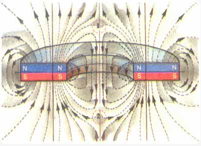
I was lately surprised to find in several sources on the internet (including PSE) the same image copied of what I believe is a wrong depiction of the inner air gap field of an axially magnetized short length ring magnet:

Ring magnet wrong field

Fig. 2 Ring Magnet cross-section inner air gap field wrongly depicted with a polarity flip (?)

This last second image above of Fig. 2 referring to the field of a short length axial ring magnet is IMHO a misinterpretation and wrong application of a technical formula for the flux density calculation of the field wrongly applied for the inner air gap of a ring magnet:

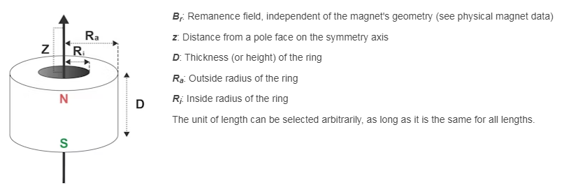
$$ B=\frac{B_r}{2}\left[\frac{D+z}{\sqrt{R_a^2+(D+z)^2}}-\frac{z}{\sqrt{R_a^2+z^2}}-\left(\frac{D+z}{\sqrt{R_i^2+(D+z)^2}}-\frac{z}{\sqrt{R_i^2+z^2}}\right)\right] $$

Formula notes

This formula is indented to calculate only the field of an axial ring magnet for a distance $z$ from the pole face of the magnet and NOT its inner air gap center origin. Somebody, took literally this equation and simulated this graph that is IMO utterly nonsense with magnetic polarity flip inside the air gap! Source link.

I have found also the source of this equation in supermagnete.de. A much more accurate simulation IMO of the field of a ring magnet can be found here from K&J magnetics. The B field is stronger at the actual ring magnet body and dims progressively inside its air gap as we approach the center. There is no magnetic polarity flip as I believe is wrongly shown in Fig. 2.

In my opinion this is a serious matter that cannot be left unanswered floating on the internet as misinformation in case it is wrong.

Nevertheless, I could be mistaken and need your expert opinion and analysis?

$\endgroup$
12
  • 1
    $\begingroup$ Whether any of those calculations perhaps has some (minor) errors would require detailed inspection, but to answer the main question: the shape of the field in Fig. 1 is wrong and in Fig. 2 it is correct. $\endgroup$ Commented May 4 at 11:24
  • $\begingroup$ Any official source for this? $\endgroup$
    – Markoul11
    Commented May 4 at 11:37
  • 1
    $\begingroup$ It's just expert opinion! (But you can understand it by applying the rule that field lines of a permanent magnet originate from the N-pole and land on the S-pole. In Fig. 1 they don't, they encircle the whole object.) $\endgroup$ Commented May 4 at 11:41
  • $\begingroup$ Thank for noticing this typo. It is now corrected to "air gap". $\endgroup$
    – Markoul11
    Commented May 4 at 12:26
  • 5
    $\begingroup$ Magnetic poles are regions where field lines enter or leave the material. This is not happening at all in figure 1, so it cannot be correct. $\endgroup$
    – my2cts
    Commented May 5 at 9:42

5 Answers 5

15
$\begingroup$

Figure 2 is the correct depiction of the magnetic field, Figure 1 is incorrect. If you look at the field lines of a regular bar magnet, and compare them to one side of the cross-section in Figure 2, they have the same basic field line behavior. One especially clear behavior is that in the horizontal plane cutting through the bar magnet, all the field lines point in the same direction. Unlike in Figure 1, where the field lines are completely different, with some field lines pointing up, and others pointing down.

$\endgroup$
7
  • $\begingroup$ Fig. 1 Illustration shows clearly all magnetic field lines going from the North pole to the South pole. I don't see these opposite vectors you are seeing? $\endgroup$
    – Markoul11
    Commented May 4 at 19:26
  • 3
    $\begingroup$ No it doesn't. Your first figure shows the magnetic field lines looping around the blue/red ring. Look at the arrows in the plane of the magnet. The arrows in the middle of the ring point up. The arrows outside the ring point down. In Figure 2, all the arrows in the plane of the magnet point down. $\endgroup$
    – BaddDadd
    Commented May 4 at 20:01
  • $\begingroup$ That's just the curl of the field closing loops from North to South! The same holds for the center field lines although this is not shown in Fig. 1. Divergence of the field must be zero. $\endgroup$
    – Markoul11
    Commented May 4 at 20:06
  • 9
    $\begingroup$ The field lines in Figure 1 are correct if the ring is a current ring. It is not, it is a permanent magnet. The field lines should come out of the top of the magnet, and go into the bottom of the magnet, just like they do for a bar magnet. Look at the two top figures at homofaciens.de/technics-electrical-engineering-magnets_en.htm. All the lines start and end on the bar magnets. None circle them. All the arrows in the middle plane point up. None point the other way. I honestly don't know what else to tell you. Figure 1 is wrong. Figure 2 is right. $\endgroup$
    – BaddDadd
    Commented May 4 at 20:48
  • 2
    $\begingroup$ Figure 2 is correct. Since you agree that Figure 1 is wrong, it would help if you could find or make another figure that you think has the correct field lines. I cannot follow your description. $\endgroup$
    – BaddDadd
    Commented May 4 at 23:58
10
$\begingroup$

In a comment you write,

In my opinion, a superposition analysis of all the vectors will result in the [correct] field …

where your assumption about the correct field is stated in the question. You're correct about the superposition analysis, but you're incorrect about the conclusion.

Let's imagine building a permanent ring magnet by putting bar magnets around the edge of a clock face, with their north poles all pointing towards us and their south poles all pointing back into the wall.

clock face

Where we stick a bar magnet at each hour number (or, if we feel ambitious, each minute number), the field comes out of the page. We're interested in the field at the center of the clock, so let's make a list:

  • The field from the magnet at 12 o'clock points into the page at the center of the clock.
  • The field from the magnet at 6 o'clock points into the page at the center of the clock.
  • The field from the magnet at 3 o'clock points into the page at the center of the clock.
  • The field from the magnet at 9 o'clock points into the page at the center of the clock.
    $\vdots$

Another approach. Let's imagine making a ring magnet by taking a cylindrical disc magnet and punching out its center.

Remember that you can think of the disc magnet as a ring of "bound current" around the perimeter, which is the explanation for a disc-shaped permanent magnet having the same field as a current ring. If you break such a permanent magnet, you reveal "bound currents" running along each of your new edges in opposite directions: they were always there, internally, but they were right next to each other, so that they cancelled out.

If we punch a smaller disc magnet out of the center of our original, the magnetized mini-disc we remove will have the bound current around its perimeter. The ring-shaped remnant, which already had one bound current around its outer perimeter, will now have another bound current around its inner perimeter, with the same current density but opposite direction around its inner perimeter. This gives you the field of nested current loops, not the field of a single loop.

$\endgroup$
1
  • 5
    $\begingroup$ I think the bound current is the most clear. The two rings of bound current go in opposite directions as you said. $\endgroup$
    – Dale
    Commented May 4 at 17:29
6
$\begingroup$

Just in case, I'll outline a quantitative approach to the problem. Just for the record, as has been already mentioned many times, fig. 2 is the correct picture.

I will consider a uniformly, axially magnetised ring, which should be an accurate model for say a neodymium magnet. It is the same as two concentric solenoids of opposing currents with uniform surface currents. It is also equivalent to two stacked annuli that are oppositely and uniformly magnetically charged. This gives you two approaches to compute the magnetic field. Technically, the charge approach gives you $H$, but outside the magnet, this is the same as $B$. The former is physically motivated while the latter is conceptually more convenient.

To make things quantitative I'll use cylindrical coordinates about the ring's axis. Say your ring has inner radius $R_i$ and outer radius $R_o$ and height $D$ and magnetisation $\vec M = M_z\vec e_z$, then the outer and inner surface current density is (using cylindrical coordinates): $$ \begin{align} \vec J_o &= M_z \vec e_\phi & \vec J_i &= -M_z \vec e_\phi \end{align} $$ while the top and bottom charge density is: $$ \begin{align} \sigma_t &= -M_z & \sigma_b &= M_z \end{align} $$ In your examples $M_z>0$. The outer surface current rotates counterclockwise and the inner surface rotates clockwise (when viewed from above). The top face is therefore positively charged and the bottom face negatively charged.

This gives you two approaches to build intuition on the qualitative behaviour of the field lines and to quantititatively calculate them. The exact formula has no simple expression and involves double integrals. It gives the same result regardless whether you use Biot-Savart's law following the current approach or Coulomb's law following the charge approach.

Both approaches explain why there is a "polarity inversion" in the "air gap" (the hole of the ring). From the current perspective, the outside surface currents generate an upward field in the gap, but the inside surface currents generate a downward field (the usual solenoid field). It is the latter that dominates after superposition since it is closer. Indeed the field decays with distance to the source, and this can be made rigorous on the axis. You can reach the same conclusion for the entire air gap with the charge perspective. You have positive charge above the gap and negative charge below, so the field is necessarily directed downwards. In either case, the result is mathematically airtight (without having to calculate exactly the field): the field points downwards in the gap.

This is consistent with your equation of $B$ on the $z$ axis. No, the formula is not meant to only be applied above the top face, it is valid on the entire axis. In fact, using the charge approach, you can trace back where each term comes from. Each annulus can be viewed as overlapping oppositely, uniformly charged disks of radius $R_i,R_o$. The four terms come from each of the four disks. Just as Coulomb's law is valid everywhere in space, this formula is valid everywhere on the axis.

From the current/magnetisation perspective, it's a bit trickier to interpret the terms. Naturally the first two terms correspond to the outer solenoid and the next bracketed to terms to the inner solenoid. In terms of magnetisation, you need to imagine the ring to be the superposition of two concentric oppositely, uniformly magnetised cylinders of respective radius $R_o,R_i$. This is why they correspond to the previous formula in your linked page. You cannot understand where the two sub terms come from as from the current/magnetization perspective, you cannot have a net magnetic charge. You can almost get there by adding and subtracting by the same constant. Essentially, a finite solenoid can be viewed as two semi infinite solenoids with an overlap and an infinite solenoid to cancel the non overlapping region. Therefore, up to an additive constant, each of the four terms can be viewed as the field of an infinite axially magnetised cylinder with a discontinuity at a certain cross section, or equivalently, an infinite solenoid with a discontinuity of the surface current at a cross section.

The general result can be plotted with any existing visualisation tool. They all confirm your "polarity flip." This backed by both of the ressources you shared: falstad and R&J magnetics.

Hope this helps.

$\endgroup$
3
$\begingroup$

This is a second answer by me, to address a different misconception from your question. You write,

$$ B=\frac{B_r}{2}\left[\left( \frac{D+z}{\sqrt{R_a^2+(D+z)^2}}-\frac{z}{\sqrt{R_a^2+z^2}} \right)-\left( \frac{D+z}{\sqrt{R_i^2+(D+z)^2}}-\frac{z}{\sqrt{R_i^2+z^2}} \right)\right] $$

Formula notes

This formula is intended to calculate only the field of an axial ring magnet for a distance 𝑧 from the pole face of the magnet and NOT its inner air gap center origin.

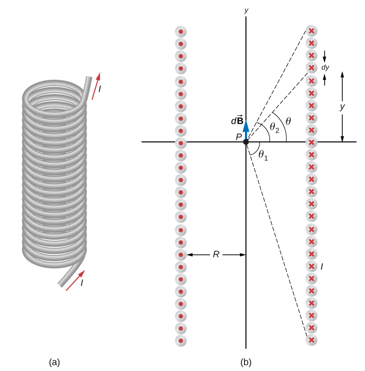
But that's just not true. A derivation of that formula includes this nice illustration of the geometry:

solenoid geometry

with angles $\theta_{1,2}$ the "viewing angles" between the point of interest and the corners of the cylinder of current. The relationship is then $$ B_\text{finite}(z) = \frac{B_\text{limiting}}{2} \left( \sin\theta_2 + \sin\theta_1 \right) $$ where $B_\text{limiting}$ is the infinite-solenoid limiting field. Of course we can use the solenoid equation to find the field on the axis of a permanently-magnetized cylinder, remembering that the cylindrical surface carries a "bound surface current," so long as we're prepared to hide from the grizzled experimentalist who wants to remind us of the differences between $\vec B$ and $\vec H$.

It's straightforward to recast the equation in your question into $$ \begin{align} B_\text{hollow}(z) &=\frac{B_r}{2}\left[\left( \frac{D+z}{\sqrt{R_a^2+(D+z)^2}}-\frac{z}{\sqrt{R_a^2+z^2}} \right)-\left( \frac{D+z}{\sqrt{R_i^2+(D+z)^2}}-\frac{z}{\sqrt{R_i^2+z^2}} \right)\right] \\&= \frac{B_r}{2} \big( \left(\sin\theta_1 + \sin\theta_2\right)- \left(\sin\phi_1 + \sin\phi_2\right) \big) \end{align} $$

with the two $\theta$ the viewing angles to the outer corners, with $R_a$ in the denominators, and the two $\phi$ the viewing angles to the inner corners, with $R_i$ in the denominators.

Whenever we have a suspicious equation like this, it's always nice to look at its behavior in some limiting cases and see whether they meet our expectations. Let's ask where the location of the field zero should be, in the parameter space $(D,R_a,R_i)$. Note this is really a two-dimensional parameter space, because the length unit is arbitrary.

  • An semi-infinite solenoid/magnet, $D\to\infty$, has the field $$ B \to \frac{B_r}{2}\left( -\frac{z}{\sqrt{R_a^2+z^2}} + \frac{z}{\sqrt{R_i^2+z^2}} \right) $$ This field has three zeros: asymptotic zeros very far from the magnet and deep inside the magnet's empty core, and a crossing zero with slope $(R_i^{-1} - R_a^{-1})$ at the mouth of the magnet. The field is positive everywhere outside the magnet, and negative everywhere inside.

    As you make the magnet length $D$ finite, the opposite-sign curve associated with the far end of the magnet pushes the field zero to some positive $z$ outside of the magnet's near end.

  • If the magnet is a thin disc with $D \ll R_i < R_a$, as in your two figures, we can ask what the field looks like in the vicinity of $z\approx R_i$. After an annoying amount of effort, I managed to find an expression which drops terms of order $\mathcal O(D/R)^2$: $$\begin{align} \frac{D+z}{\sqrt{R^2+(D+z)^2}} %&= \frac{ \frac zR\cdot(1+\frac Dz) }{ \sqrt{ 1 + \left(\frac zR\right)^2\left(1 +2 \frac Dz \color{lightgray}{{}+ \mathcal O\left(\frac Dz\right)^2}\right)}} \\ %&=\frac{\frac zR}{\sqrt{1 + \left(\frac zR\right)^2}}\cdot \frac{1 + \frac Dz}{\sqrt{1 + 2\frac Dz\left(1 + \left(\frac zR\right)^2\right)^{-1}}} \\ %&=\frac{z}{\sqrt{R^2+z^2}}\cdot\frac{1 + \frac Dz}{\sqrt{1 + 2\frac Dz\frac{z^2}{R^2+z^2}}} \\ %&\approx \frac{z}{\sqrt{R^2+z^2}}\cdot\left( 1 + \frac Dz\right)\cdot\left( 1 - \frac 22\frac Dz \frac{z^2}{R^2+z^2} \color{lightgray}{{}+ \mathcal O\left(\frac Dz\right)^2} \right) \\ %&= \frac{z}{\sqrt{R^2+z^2}}\cdot\left( 1 + \frac Dz \frac{R^2}{R^2+z^2} \color{lightgray}{{}+ \mathcal O\left(\frac Dz\right)^2} \right) \\ &\approx \frac{z}{\sqrt{R^2+z^2}} + \frac DR \left(\frac{R}{\sqrt{R^2+z^2}}\right)^3 \end{align} $$ This approximation gives a field $$ \begin{align} B &\approx \frac{B_r}{2} \cdot\left( \frac D{R_a}\left(\frac{R_a}{\sqrt{R_a^2+z^2}}\right)^3 - \frac D{R_i}\left(\frac{R_i}{\sqrt{R_i^2+z^2}}\right)^3 \right) \end{align} $$ I had hoped this would give an expression for the location of the field zero for a thin-disc ring magnet in terms of $R_i/R_a$, but setting $B=0$ gives a cubic polynomial in $z^2$ whose roots I'm not able to interpret in a sensible way. Some numerical analysis suggests that, in the limit of a very thin annulus $R_i\to R_a$, the zero in the field approaches $z=\frac 23 R_a$.

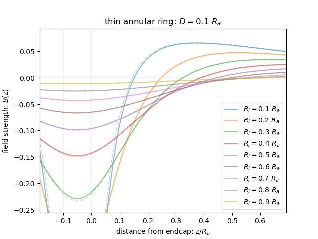
    data plot

    Here's a plot of the field where this thin-disc limit starts to be useful, with the thickness of the ring at 10% of its outer radius. The different curves are for different inner radii. The reversed field (on axis) gets stronger as the hole gets smaller. The solid curves are the exact expression from your question. The dashed curves are the cubic approximation that didn't turn out to be helpful, but they are good approximations, so at least that slog wasn't fruitless and wrong.

These two limits actually show us the behavior of the field over the entire parameter space. The field in the hollow core of the ring magnet is always opposite the magnetic moment of the ring magnet. As the ring magnet gets shorter, from a cylinder to a disc, the reverse-direction field leaks out of the end somewhat, but never further than about two-thirds of the radius of the ring.

$\endgroup$
6
  • $\begingroup$ Thanks for your canonical answer. and I agree with your analysis. If you read the legend under the equation it defines parameter z as, "Distance from the pole face on the symmetry axis". Therefore, the manufacturer has no intend to use this formula for calculating the inner field in the hole of the ring. Unless, a third party simulation of the formula we cannot confirm if this formula holds also for negative z axis values. $\endgroup$
    – Markoul11
    Commented May 6 at 9:29
  • $\begingroup$ About my answer on this question thread. my experiment result shows that for macroscopic experiments and interaction with comparable size magnets to the ring magnet, the field of Fig.1 is the dominant field and interaction with other magnetic objects independent of distance. The magnetic polarity flip at the hole has no real effect in this case and can be neglected. The net effect is that the two magnets pole faces will attract or repel all the distance up to zero without experiencing any polarity flip. This is an experimental result that confirms Fig.1 field depiction of the ring magnet. $\endgroup$
    – Markoul11
    Commented May 6 at 9:47
  • $\begingroup$ @Markoul11 A "third party simulation" is exactly what I've created for you here. The expression in your question follows directly from the Biot-Savart law, with details available in the link or in most other textbooks on electromagnetism. If you read my answer you notice that I also define $z$ as the distance from the endcap of the magnet. This convention makes $z=0$ correspond to $\theta_2=0$. You'll also notice that the field lines in my plot are symmetric around $-D/2 = -0.05R_a$, the center of the magnet. $\endgroup$
    – rob
    Commented May 6 at 13:54
  • $\begingroup$ I meant a simulation reproducing and verifying the Fig. 2. But yes I appreciate your answer and therefore I have upvoted it. $\endgroup$
    – Markoul11
    Commented May 7 at 8:18
  • $\begingroup$ I'm really confused by your approach to this question. There is an answer posted to this question which reproduces your Figure 2. It's the answer that you wrote. But, because the reversed-field region is smaller than some field probe you currently have in your lab, you seem to have decided that it's not important. I didn't understand the question to be about whether the reversed-field region was important to you personally; I thought you were asking whether it exists at all. This answer sketches the minimum volume of reversed field for all values of $D/R_a$ and $R_i/R_a$. $\endgroup$
    – rob
    Commented May 7 at 15:36
-4
$\begingroup$

Experiment Verification

I did some further experiments using a small 3mm square 1mm thick square plate magnet on a 30mm outer diameter, 15mm inner diameter and 8mm height (i.e. length) N36 grade ferrite ring magnet.

Result: Both Fig 1 and Fig.2 are correct for a relative short length axially magnetized ring magnet:

$(1)$ The field illustration of Fig. 1 of the question, represents the macroscopic far-field of the ring magnet on air, for point measurement distances from the inner center of the ring magnet larger than approximately the inner radius of the magnet thus in the case of this experiment for measurement points at distances $R_{m}>7.5mm$ from the inner center of the magnet.

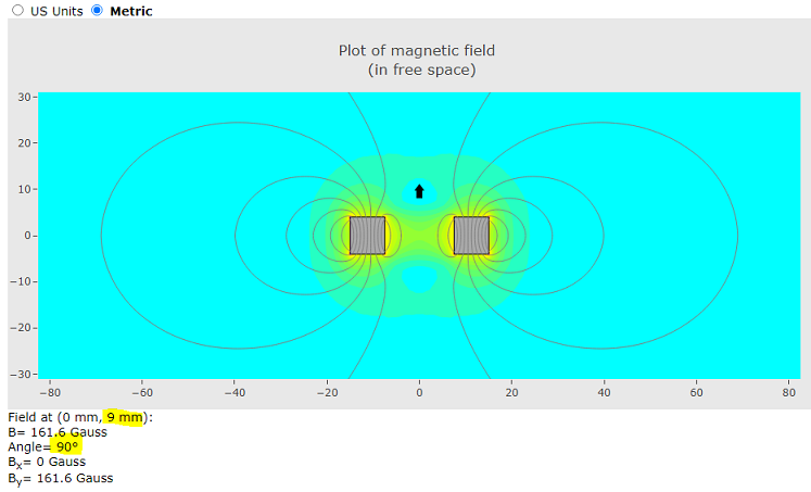
This can be also confirmed as LPZ mentioned using the K&J simulator for the above specified magnet, see below for distance $R_{m}=9mm$,

test 1

Black arrow shows point measurement position and also North magnetic polarity (i.e. arrow points up).

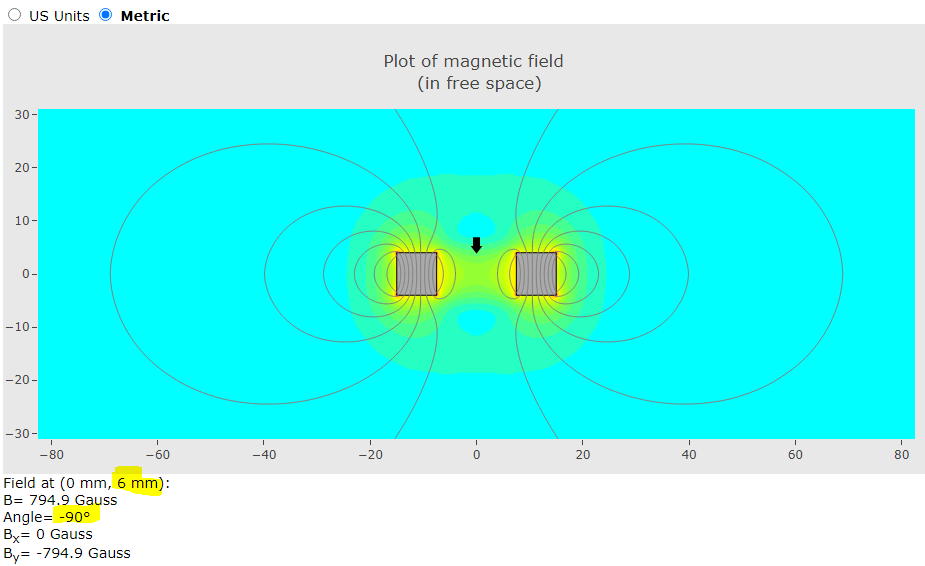
$(2)$ The field of Fig. 2 represents the microscopic near-field of the ring magnet on air, for point measurement distances from the inner center of the ring magnet smaller than approximately the inner radius of the magnet thus in the case of this experiment for measurement points at distances $R_{m}<7.5mm$ from the inner center of the magnet. In this case, yes indeed I have observed a polarity flip by using a second 3mm and 1mm thick square plate neodymium magnet N42 grade in the center hole area of the ring magnet as correctly shown in Fig. 2 of the question.

test 2

Black arrow shows point measurement position and also South magnetic polarity (i.e. arrow points down). Measurement point taken at $R_{m}=6mm$ distance from inner center of ring magnet.

Note: Also please notice here that a second magnet of similar or larger size than our experiment ring magnet will always sense the macroscopic field of the ring depicted in Fig. 1 independent its separation distance from the ring magnet. For example, I have repeated the experiment with a 3 cm long magnetic compass needle and approached it as closely as I could (less than 4mm from inner center of the ring magnet) and I did not observe a flip in the orientation of the compass needle. This is logical since the macroscopic far-field of the ring magnet is the one that interacts more dominant with the whole length of the compass needle. Likewise, any permanent magnetic object of comparable size with the ring magnet will sense the macroscopic field on air illustrated in Fig. 1 of the ring magnet and NOT its near-field microscopic field shown in Fig. 2. Only when the size of the second magnet is much less than that of the ring magnet's pole face then case (2) above holds and the small magnet experiences a polarity flip when in close proximity to the center area of the ring magnet.

Conclusion: Both Fig. 1 and Fig. 2 of the question are correctly representing accordingly the macroscopic far-field on air and the microscopic near-field of an axially magnetized relative short length ring magnet. Under these experiment observations, we can say that the macroscopic far-field of such a ring magnet shown in Fig. 1, is a good approximation of the magnetic field of a single current loop.

Update 6 May 2024

About my answer on this question thread, my experiment result shows that for macroscopic experiments and interaction with comparable size magnets to the ring magnet, the field of Fig.1 is the dominant field and interaction with other magnetic objects independent of distance. The magnetic polarity flip shown in Fig. 2 of the question at the hole has no real effect in this case and can be neglected. The net effect is that the two magnets pole faces will attract or repel all the distance up to zero without experiencing any polarity flip confirmed in all my experiments with comparable size magnets to the ring magnet. This is an experimental result that confirms Fig.1 macroscopic field depiction of a short length axially magnetized ring magnet.

Downnvoting this answer will not change these experiment results and their conclusions.

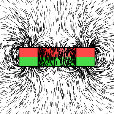
Simulated iron filings field depiction of the total cross-section field on air of a ring magnet:

Simulated iron filings

Credits: https://commons.wikimedia.org/wiki/File:Ironfilings_ringmagnet.svg

Note: The strongest dominant part of the field shown in above image is the one closer to the bulk material (i.e. body) of the ring magnet.

$\endgroup$
12
  • $\begingroup$ Use a very small magnet on a relatively large ring magnet. For example, as you approach the small magnet towards the center of the ring magnet from a far distance you first will experience with your hand attraction but as you closing in you will experience repulsion and vice versa when you use the other pole face of the ring magnet (i.e. first repulsion at far and then attraction at close proximity). $\endgroup$
    – Markoul11
    Commented May 5 at 13:44
  • $\begingroup$ IMO. in general and most macroscopic experiments, the field of Fig. 1 is the dominant field of a ring magnet and you can safely dismiss the polarity flip shown in Fig. 2 as having no real effect to the final outcome of the experiment. $\endgroup$
    – Markoul11
    Commented May 5 at 14:06
  • 1
    $\begingroup$ I want to like this answer, because it's great that you've done a calculation and an experiment. But your conclusion is wrong. The transition between the near-field and far-field regions is already shown in you question's Figure 2. That figure shows low-field quadrupole transition regions in little red circles, one of which corresponds to the low-field blue circle where your answer has drawn little black arrows. $\endgroup$
    – rob
    Commented May 5 at 14:16
  • 1
    $\begingroup$ You write "The field of Fig. 2 represents the microscopic near-field of the ring magnet on air, for point measurement distances from the inner center of the ring magnet smaller than approximately the inner radius of the magnet". Your emphasis on "microscopic" and on "smaller" distances implies that Figure 2 is only correct in those cases. You should edit your answer to include that Figure 2 is generally correct, including at macroscopic distances. $\endgroup$
    – BaddDadd
    Commented May 5 at 16:51
  • 5
    $\begingroup$ @Markoul11 this is all macroscopic. The term microscopic is incorrect anywhere in this question and answer as it has a standard meaning in EM that is not what you are using it for here. The correct term is near field, not microscopic. $\endgroup$
    – Dale
    Commented May 6 at 11:55

Your Answer

By clicking “Post Your Answer”, you agree to our terms of service and acknowledge you have read our privacy policy.

Not the answer you're looking for? Browse other questions tagged or ask your own question.