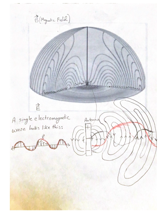
I have read about wave propagation and dipole antennas here. I do not understand how a single electromagnetic wave (i.e. the electric field in particular - I can come up with the magnetic field later) propagates when its electric field of a dipole antenna is shown below. For example, the iconic picture of an electric field of an electromagnetic wave looks like the figure in the bottom left corner in red below. How does it look in the bottom right diagram? I tried to plot it below again in red, but it doesn't make sense to me. For example, the amplitude of the wave would get bigger. So, I would like to know how a single electromagnetic wave propagates in this field.
-
$\begingroup$ It would seem you want to decompose radiation from a dipole source into a combination of plane waves. en.wikipedia.org/wiki/Plane-wave_expansion . The link is for a scalar case, but vector-waves can also be handled in a similar fashion. Is this what you are after? $\endgroup$– CryoCommented Nov 20, 2023 at 15:23
-
$\begingroup$ en.wikipedia.org/wiki/Weyl_expansion is the reverse $\endgroup$– CryoCommented Nov 20, 2023 at 15:24
-
$\begingroup$ That is partly what I am looking for. I am looking for how to compose that plane wave but not with an equation. I'm looking for how to draw it in context of the picture. $\endgroup$– William GarskeCommented Nov 20, 2023 at 15:28
-
$\begingroup$ Many plane waves, with many amplitudes and phases go in all directions. I doubt the picture will look nice. $\endgroup$– CryoCommented Nov 20, 2023 at 16:13
-
$\begingroup$ Don't forget also that amplitude of the plane wave does not have a length in the physical space. You drew your red/black amplitudes of the size similar to dipole. Well electric field is measured in Volt/meter, whilst antenna size is in meters. You cannot compare them $\endgroup$– CryoCommented Nov 20, 2023 at 16:21
4 Answers
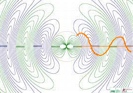
Keep in mind that the magnitude of the field is modeled by the density of the field lines, but not by their size.

(using an image from Visualizing dipole radiation)
So the field magnitude (the orange line drawn by me) of the EM wave can (and does) decrease with the distance from the dipole antenna.
-
$\begingroup$ I now get that $\lambda$ can easily be concluded from this. Are there an infinite number of those EM waves that radiate outward? Like do they all have different amplitudes sometimes being a mile long and other times being a few meters? $\endgroup$ Commented Nov 20, 2023 at 17:34
-
1$\begingroup$ @WilliamGarske Do you mean different EM waves from different antennas? Sure there are. Think of a radio station transmitting at $\lambda=3$ m, and at the same time a cell phone transmitting at $\lambda=0.2$ m. All their transmitted waves superimpose, adding up to one single electromagnetic field. $\endgroup$ Commented Nov 20, 2023 at 17:57
-
$\begingroup$ I mean one antenna. Are there an infinite number of these EM waves that propagate outward? Specifically, looking at the drawing you made $\endgroup$ Commented Nov 20, 2023 at 18:22
-
1$\begingroup$ @WilliamGarske I'm not sure what you mean by multiple EM waves. I would say, there is just one EM field $\vec{E}(\vec{r},t)$ and $\vec{B}(\vec{r},t)$, i.e. having a different value at every position $\vec{r}$ and time $t$. This EM wave spreads out from the center into all directions, thus filling all space. There is no need for the concept of multiple EM waves. $\endgroup$ Commented Nov 20, 2023 at 18:54
An EM wave is generated by the synchronous acceleration of surface electrons on a conductor rod. To prevent the process from coming to a standstill, it is periodically reversed. The electrons are moved towards the end of the rod and then back again.
Photons are emitted during the acceleration processes. This is perpendicular to the rod axis and always with alternating magnetic and electric field components along the direction of propagation, i.e. exactly according to the field lines in your sketch. The density of the photons naturally decreases with the distance to the rod.
At a receiver, the impact of an absolutely small quantity of the emitted photons is sufficient to reconstruct the EM wave. This is because the incoming photons are absorbed by the surface electrons of the receiver conductor and the electrons are moved in the conductor. This current is sufficient to detect a specific EM wave. (By tuning with a resonant circuit, other sources are filtered out and music/speech/information can be transmitted by frequency modulation. Easy to research on the net).
EM radiation is the chaotic emission of photons and occurs constantly and everywhere where an energy difference is equalised. EM waves are based on the synchronised and periodic emission of photons. You can assign a graph to the intensity of the wave between the emitter and absorber (i.e. also to a measuring instrument at any point in space), which shows the wave-like progression of the intensity. The intensity always decreases from the source to the sink. Exactly as you have drawn it but with lowering amplitude.
Your wiggly red line represents the magnitude of the field, not a physical motion. Its amplitude declines with distance from the antenna.
-
$\begingroup$ That makes sense. But how does a single electromagnetic wave travel in that field then? $\endgroup$ Commented Nov 20, 2023 at 15:19
-
$\begingroup$ You mean a plane wave? An antenna doesn't make plane waves, but a wave may appear to be a plane wave far from the antenna that produces it. Plane waves are a typical textbook abstraction: they don't make perfect sense in the real world. $\endgroup$ Commented Nov 20, 2023 at 15:26
-
$\begingroup$ So, are you saying that it doesn't make sense to talk about the wave on the left? When they talk about radio waves having a specific amplitude then, what do they mean? $\endgroup$ Commented Nov 20, 2023 at 15:36
-
$\begingroup$ I think there is a far-field region where those are the waves. I still don't quite understand it: mvg-world.com/en/manual/antenna-measurement-101/…. $\endgroup$ Commented Nov 20, 2023 at 15:51
-
$\begingroup$ The amplitude is what you measure with a device that senses the electric field. The wiggly line is a plot of the field versus position. In the far field, the waves are approximately plane. $\endgroup$ Commented Nov 20, 2023 at 16:04
Imagine we suddenly inject some spare electrons into a piece of wire. Current flows for a moment as the wire charges up and an electric field is propagated away from the wire at the speed of light and zooms off to infinity. The fact that the electric field is changing continuously as the wire charges up means a magnetic field is also emitted and we have thus created a pulse of EM radiation moving away from the wire. When the wire is fully charged up, the electric field is no longer varying and the magnetic field dies out and the wire ceases to radiate electromagnetically.
We use this behavior to propagate EM waves by reversing the flow of current at or before that moment when the wire reaches full charge. Now the wire is radiating an EM field where the electric and magnetic components are reversed in sign, and away goes the wave: a trough instead of a peak like the first pulse that left the wire.
This whole topic is well-modeled by antenna theory, which you can learn more about on the Amateur Radio Stack Exchange.

