0
$\begingroup$

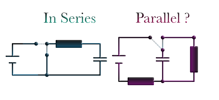
Pretty basic stuff, but to be honest I haven't found a circuit diagram showing a capacitor discharging in parallel.

The only scheme I can come up with is shown here: $\color{gray}{\textbf{[ Edited ]}}$

enter image description here

I'm assuming a fully charged capacitor at $t = 0$

However the parallel one actually looks like the one in series. The only difference appears to be that Capacitor and Resistor have change placed, but current should still flow as if they are directly connected in series circuit.

$\textbf{So: Is there any way a capacitor can discharge in parallel?}$

Also depending on on what circuit it leads to different formula:

$$\begin{align}\textsf{[discharging]} \\[12pt] \textbf{Series:} && 0 = U_R + U_C & \Rightarrow & 0 = R\,\dot{Q}_C + Q/C \\[12pt] \textbf{Parallel:} && I = I_R + I_C & \Rightarrow & I = U/R+ \dot{U}\,C \end{align} $$

$\endgroup$
4
  • 1
    $\begingroup$ The vertical wires in your two left hand diagrams will short-circuit the battery when you close the switch. The battery will get hot (perhaps dangerously so) and will quickly lose almost all its stored energy. The wire can have almost zero voltage across it, even when the switch is closed and current is going through it, because its resistance will be very small. So the capacitor will gain no charge when the switch is closed. Get rid of those vertical wires, and then we can discuss the circuits usefully. $\endgroup$ Commented Aug 1, 2022 at 18:55
  • 2
    $\begingroup$ Your first diagram short circuits the battery. Your second diagram lacks resistance in series to limit the capacitor charging current needed to prevent damage to the capacitor $\endgroup$
    – Bob D
    Commented Aug 1, 2022 at 19:32
  • $\begingroup$ Thank you for your hints. I have edited the diagram. It is just a theoretical one so no real components can be damaged. The question remains: Can a capacitor be discharged in parallel ? $\endgroup$
    – Leon
    Commented Aug 2, 2022 at 14:11
  • $\begingroup$ "Discharging in parallel" is not a thing. And neither is "discharging in series". Both circuits shown in the OP are the same when the switch is in the discharging position. $\endgroup$
    – nasu
    Commented Aug 2, 2022 at 14:51

2 Answers 2

1
$\begingroup$

For your circuits, to discharge the capacitor it must be disconnected from the charging source. What is left is a capacitor connected to a single resistor. The questions are:

  1. In the circuit labeled Series, are the resistor and capacitor in series or in parallel. (Ignore the switch and battery)
  2. In the circuit labeled Parallel, are the resistor and capacitor in series or in parallel. (Ignore the switch, battery and resistor in series with the battery.)

How can it be determined: If two components are in parallel, then their voltage drops are equal. This is true in both circuits while discharging. If two components are in series, then their currents are equal. This is true in both circuits while discharging. So we must conclude that the two components are both in series and in parallel at the same time.

Laying things out on paper so that they look in series or in parallel on the can be misleading. We must look to the electrical connections to confirm.

In order to discharge, a capacitor applies its voltage in parallel to a load resistance. The load resistance draws current in series with the capacitor. All discharges can be considered this way.

$\endgroup$
1
$\begingroup$

If you call a capacitor in row with a resistor or parallel does nor matter. the two end of C have to be connected over some resistor to discharge it. So th current flowing away from C is th one flowing through R. So the equation you put for parallel is not possible.

$\endgroup$

Your Answer

By clicking “Post Your Answer”, you agree to our terms of service and acknowledge you have read our privacy policy.

Not the answer you're looking for? Browse other questions tagged or ask your own question.