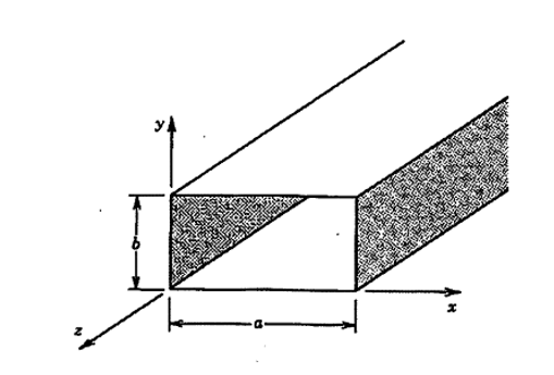
Shown below Figure 9-1 from 1 (an excellent reference book) where you can see the qualitative behaviors of some commonly used slot arrangements, radiating v. non-radiating, for the $TE_{10}$ mode.
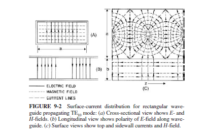
The reason for the expected behavior is explained in the following Figure 9-2 showing the surface currents on the walls and quoted text.
Narrow slots that are parallel to waveguide wall currents do not radiate. However, when a slot is cut into a waveguide wall and it interrupts the flow of current, forcing it to go around the slot, power is coupled from the waveguide modal field through the opening to free space.
and
Rotating the slot with respect to a peak current direction can control the power coupled to a slot. For example, slot e couples maximum power, while the power is proportional to $sin^2 \phi$ for slots d and c. Another way to control coupled power is to take advantage of the natural field intensities within the waveguide by locating the slots accordingly. For example, $J_x$ is a null at the center of the surface wall and varies sinusoidally as you approach the edge. Therefore, by offsetting longitudinal slots such as slot a from the center of the waveguide, the power coupled to the slots can be adjusted.


-------
1 Volakis: Antenna Engineering Handbook, 4th ed
(here is the current 5th edition https://www.amazon.com/Antenna-Engineering-Handbook-John-Volakis/dp/1259644693/ref=sr_1_1?dchild=1&keywords=Volakis%3A+Antenna+Engineering+Handbook&qid=1598269068&sr=8-1 and it appears that the quoted text/Figure is now in chapter 16 of this edition)


