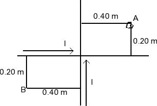
First, find the electric and magnetic fields generated by the individual wires. You have probably already done this if you are working on this problem, but if not, they are easy to find using a Gaussian surface and an Amperian loop:
$$ \oint \mathbf{E}\cdot d\mathbf{a} = \frac{Q_{enc}}{\epsilon_0} \quad\quad\quad\quad \oint \mathbf{B}\cdot d\mathbf{l} = \mu_0 I_{enc}$$
Once you have found the electric/magnetic fields generated by each wire individually, choose one wire (call it wire 1) and determine the force it imparts on the other (wire 2) using the Lorentz force law:
$$ \mathbf{F} = q(\mathbf{E}+\mathbf{v}\times\mathbf{B}) $$
(Where $\mathbf{v}$ is the velocity vector of the charge). Notice, however, that the force on wire 2 is not constant along the wire, so you'll have to look at each little segment $d\mathbf{l}$ of wire 2 separately. In each little segment there is a charge $\lambda dl$ (where $\lambda$ is the charge density on wire 2, and $dl$ is the magnitude of $d\mathbf{l}$). Thus, for this little piece of wire 2, the Lorentz force law becomes
$$ d\mathbf{F} = \lambda dl(\mathbf{E}+\mathbf{v}\times\mathbf{B}) $$
(Now $\mathbf{v}$ is the velocity vector of the charge in the little segment $d\mathbf{l}$ that you're looking at). If you look at the part $\lambda dl(\mathbf{v}\times \mathbf{B})$, you should recognize $\lambda \mathbf{v}$ as a current. Now we have
$$ d\mathbf{F} = dl(\lambda \mathbf{E}+\mathbf{I}\times\mathbf{B}) $$
(Recall that $\mathbf{I}$ is the current vector, which in your case is the same for every little segment $d\mathbf{l}$). Now we just have to think about what's going on. As you march down wire 2, each little segment that you pass (of length $dl$) experiences the force above (which you can calculate explicitly once you have found $\mathbf{E}$ and $\mathbf{B}$). Therefore to get the total force on wire 2 you would just integrate the above for all of wire 2. You should find that $\mathbf{E}$ and $\mathbf{B}$ depend on $s$, so you should think about the relationship between $dl$ and $ds$.
I hope this helps get you started.

