As Whit3rd points out in his comment, the answer is it depends. For example, if your copper wire is electromagnetically shielded, the radiated power is essentially zero. Even if it's not shielded the environment does play a role in the amount of EM radiation produced by the wire. However, I assume that what you really mean is a copper wire in free space, without anything else in the region.
In the frequency ranges you're talking about, the current distribution in such a wire is a wave $I(z,t)$ , and whether this wave is a travelling wave or standing wave depends on the termination. Thus, the radiation also depends on the termination of your wire, because the current distribution depends on it. Let's consider a matched line in which the current is a pure travelling wave. The current distribution (in phasor representation) for the wire is:
$I(z) = I_0 e^{-ikz}$, where $k=\omega \sqrt{\mu_0 \epsilon_0}$ is the free space wavenumber. Note that we are assuming a very thin wire for simplicity. We can first calculate the vector potential in the farfield approximation using the retarded potential:
$$\mathbf A(\mathbf x) = \frac {\mu_0 \hat {\mathbf z}}{4 \pi} \int_{\mathbb R} I(z') \ \frac {e^{-i k|\mathbf x-z' \hat {\mathbf z}|}}{|\mathbf x-z' \hat {\mathbf z}|} dz'\simeq \frac {\mu_0 \hat {\mathbf z}}{4 \pi}\frac{e^{-ikr}}{r} \int_{-l/2}^{l/2} I_0e^{-ikz'} \ e^{ikz'\cos\theta} \ dz' = \frac {\mu_0 I_0 l \ \hat {\mathbf z}}{4 \pi}\frac{e^{-ik_0r}}{r} \frac{\sin[\frac l2 (k \cos \theta + k))]}{\frac l2 (k \cos \theta + k))} $$
Thus, the electric field in the far-zone is:
$$\mathbf E(\mathbf x) = - \boldsymbol \nabla \phi (\mathbf x) - i \omega \mathbf A(\mathbf x) \simeq - i \omega \mathbf A_{\theta}(\mathbf x)= i \omega \frac {\mu_0 I_0 l \ \hat {\boldsymbol \theta}}{4 \pi}\frac{e^{-ikr}}{r} \sin\theta \frac{\sin[\frac l2 (k \cos \theta + k))]}{\frac l2 (k \cos \theta + k))}$$
And the Poynting vector:
$$\mathbf S(\mathbf x)=\frac {\hat {\mathbf r}}{2 \eta} \mathbf E(\mathbf x). \mathbf E^*(\mathbf x)= \frac {\hat {\mathbf r}}{2 \eta}\omega^2 \frac {\mu_0^2 I_0^2 l^2 \ }{16 \pi^2}\frac{1}{r^2} \sin^2\theta\frac{\sin^2[\frac l2 (k \cos \theta + k))]}{[\frac l2 (k \cos \theta + k))]^2}$$
Now we can derive the total radiated power by integrating the Poynting vector over some closed surface (which is taken to be a sphere for convenience):
$$P_{rad}=\oint_S \mathbf S.d \mathbf a= \frac 1{2 \eta}\omega^2 \frac {\mu_0^2 I_0^2 l^2 \ }{16 \pi^2} \int_{4\pi} d\Omega \sin^2\theta \frac{\sin^2[\frac l2 (k \cos \theta + k))]}{[\frac l2 (k \cos \theta + k))]^2}$$
$$P_{rad}=\frac 1{2 \eta}\omega^2 \frac {\mu_0^2 I_0^2 l^2 \ }{8 \pi} \int_0^{\pi} \sin\theta (1-\cos^2\theta) \frac{\sin^2[\frac l2 (k \cos \theta + k))]}{[\frac l2 (k \cos \theta + k))]^2}d\theta$$
Using the change of variables $u=\frac l2 (k \cos \theta + k) $:
$$P_{rad}=\frac 1{2 \eta}\omega^2 \frac {\mu_0^2 I_0^2 l^2 \ }{8 \pi} \frac 2{lk} \int_{0}^{lk} \biggr(1-\bigr(\frac {2u-kl}{kl}\bigr)^2\biggr) \frac{\sin^2u}{u^2}du$$
By looking up the above integral, the final result is:
$$P_{rad}=\frac { \eta \ }{8 \pi} I_0^2 \biggl[\frac 1{kl} \biggr(2kl(-Ci(2kl)+\ln(kl)+\gamma-1+\ln 2)+\sin(2kl)\biggr)\biggl]$$
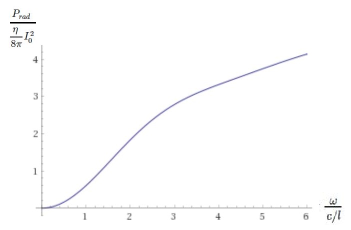
Where $Ci(x)$ is the cosine integral function, and $\gamma \simeq 0.577216$ is the Euler-Mascheroni constant. To check our answer, we can plot this result as a function of (normalized) frequency $\frac {\omega}{c/l}=kl$ using Wolfram Alpha:
 Which is monotonically increasing with frequency, with $P_{rad}=0$ for DC currents; as expected!
Note the following:
1) We have assumed a single current carrying wire. For something like a two wire transmission line, as long as the separation of the two wires is negligible compared to the wavelength, the radiation of the two wires cancel out in the far-field. For cases in which the separation is not negligible one can use array theory to calculate the electric field of the two wires from the individual wire relations derived here.
2) As your numerical example, you have considered a 1 meter wire with a voltage difference of 1 volt and a current of 1 ampere (I assume that you are giving the amplitudes, not the RMS values). You can't assume both the current and the voltage when radiation losses are present. The radiation resistance of the wire (plus the actual resistance) relates these two quantities together. In your numerical example, for a current of 1 A (which is HUGE at 1 GHz), plugging in the numbers gives $P_{rad} \simeq 100 W$ ! So your radiation resistance is $R_{rad}= \frac {2 P_{rad}}{I_0^2} = 200 \ \Omega $. Which means you will need at least a voltage of $V=R_{rad}I_0=200 \ V$ to run a current of 1 A ! This is just a lower bound, because we have not taken the copper resistance of the wire into account.
3) If you are not sure about the justification for some of my approximations in the farfield, such as $\mathbf E = - \boldsymbol \nabla \phi - i \omega \mathbf A \simeq - i \omega \mathbf A_{\theta}$. Check any book antenna theory. My personal recommendation is Antenna Theory and Design by R.S.Elliott. You can also checkout these lecture notes.
4) If anyone notices a mistake in my calculations, please notify me. I would very much appreciate it.
Answer to update 1:
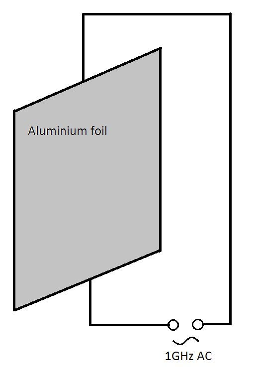
One can also calculate the radiated power of a sheet of surface current (although it needs a bit more effort). By your assumption of uniform surface current density in the sheet (S), $\mathbf J_s(\mathbf x)=J_0 \ \hat {\mathbf x}$ (I am picking my coordinate system such that the sheet lies in the x-y plane, and the current flows in the x direction). Similar to what was done for the wire, we have:
$$\mathbf A(\mathbf x) = \frac {\mu_0 }{4 \pi} \int_{S} \mathbf J_s(\mathbf x') \ \frac {e^{-i k|\mathbf x-\mathbf x'|}}{|\mathbf x-\mathbf x'|} d^2\mathbf x' \simeq \frac {\mu_0 J_0 }{4 \pi } \ \hat {\mathbf x} \ \frac{e^{-ikr}}{r} \int_{S} e^{i k \ \hat {\mathbf r}.\mathbf x'} d^2\mathbf x' $$
In Cartesian coordinates, this is:
$$\mathbf A(\mathbf x)\simeq \frac {\mu_0 J_0 }{4 \pi } \ \hat {\mathbf x} \ \frac{e^{-ikr}}{r} \int_{- \frac a2}^{ \frac a2}dx' \int_{- \frac b2}^{ \frac b2} dy' e^{i k (x' \sin\theta \cos\phi + y'\sin\theta\cos\phi)}=\frac {\mu_0 J_0 }{4 \pi} \ \hat {\mathbf x} \ \frac{e^{-ikr}}{r} \int_{- \frac a2}^{ \frac a2}e^{i k ( \sin\theta \cos\phi)x'}dx' \int_{- \frac b2}^{ \frac b2} e^{i k ( \sin\theta\cos\phi)y'}dy'$$
So the vector potential is :
$$\mathbf A(\mathbf x)\simeq\frac {\mu_0 J_0 A }{4 \pi } \ \hat {\mathbf x} \ \frac{e^{-ikr}}{r} \ \frac{ \sin\bigr(k \frac {a}{2}(\sin\theta\cos\phi)\bigr)}{k \frac {a}{2}(\sin\theta\cos\phi)} \frac{ \sin\bigr(k \frac {b}{2}(\sin\theta\sin\phi)\bigr)}{k \frac {b}{2}(\sin\theta\sin\phi)}$$
And the electric field:
$$\mathbf E(\mathbf x) = - \boldsymbol \nabla \phi (\mathbf x) - i \omega \mathbf A(\mathbf x) \simeq - i \omega \mathbf A_{T}(\mathbf x)=- i \omega (\mathbf A_{\theta}(\mathbf x)+\mathbf A_{\phi}(\mathbf x))$$
$$\mathbf E(\mathbf x) \simeq -i\omega \frac {\mu_0 J_0 A }{4 \pi} (\cos\phi\cos\theta \ \hat {\boldsymbol \theta}-\sin\phi \ \hat {\boldsymbol \phi}) \ \frac{e^{-ikr}}{r} \ \ \frac{ \sin\bigr(k \frac {a}{2}(\sin\theta\cos\phi)\bigr)}{k \frac {a}{2}(\sin\theta\cos\phi)} \frac{ \sin\bigr(k \frac {b}{2}(\sin\theta\sin\phi)\bigr)}{k \frac {b}{2}(\sin\theta\sin\phi)}$$
The Poynting vector:
$$\mathbf S(\mathbf x)=\frac {\hat {\mathbf r}}{2 \eta} \mathbf E(\mathbf x). \mathbf E^*(\mathbf x)=\frac {\hat {\mathbf r}}{2 \eta}\omega^2 \frac {\mu_0^2 J_0^2 A^2\ }{16 \pi^2}\frac{1}{r^2} (\cos^2\theta \cos^2\phi+\sin^2\phi)\frac{ \sin^2\bigr(k \frac {a}{2}(\sin\theta\cos\phi)\bigr)}{[k \frac {a}{2}(\sin\theta\cos\phi)]^2} \frac{ \sin^2\bigr(k \frac {b}{2}(\sin\theta\sin\phi)\bigr)}{[k \frac {b}{2}(\sin\theta\sin\phi)]^2}$$
Total radiated power:
$$P_{rad}=\oint_S \mathbf S.d \mathbf a=\frac {\eta}{2}k^2 \frac { J_0^2 A^2 \ }{16 \pi^2} \int_{4 \pi} d\Omega \ (\cos^2\theta \cos^2\phi+\sin^2\phi)\frac{ \sin^2\bigr(k \frac {a}{2}(\sin\theta\cos\phi)\bigr)}{[k \frac {a}{2}(\sin\theta\cos\phi)]^2} \frac{ \sin^2\bigr(k \frac {b}{2}(\sin\theta\sin\phi)\bigr)}{[k \frac {b}{2}(\sin\theta\sin\phi)]^2}$$
$P_{rad}=\eta \frac { J_0^2 \ }{8 \pi^2 k^2} \int_0^{2 \pi} d\phi \int_0^{\pi} d\theta \sin\theta \ (\cos^2\theta \cos^2\phi+\sin^2\phi)\frac{ \sin^2\bigr(k \frac {a}{2}(\sin\theta\cos\phi)\bigr)}{(\sin\theta\cos\phi)^2} \frac{ \sin^2\bigr(k \frac {b}{2}(\sin\theta\sin\phi)\bigr)}{(\sin\theta\sin\phi)^2}$
As you can probably see, the above integral is far too complicated to be calculated by hand. I suggest plugging in your numbers and solving the integral numerically with some software package (e.g. MATLAB).
I should probably also tell you that I have no idea on how to make the current uniform in such a sheet, as its current would also have a wave behavior $\mathbf J_s=J_0 e^{-ikz} \hat {\mathbf x}$; and that is also not necessarily how the current distribution will be in practice, because the distribution highly depends on where you exactly feed current through it. But as you can see even the simplest case of a uniform current is really hard to solve.
Also, if you want to stop your circuit from radiating, you can always electromagnetically shield it.


