47
$\begingroup$

As the main title says. I'm finding myself wondering about helicopters. The tail rotor is a vulnerable and key piece of equipment, especially on military helicopters. I know some helicopters instead use two main rotors (for example the KA-50).

Why not use a reaction wheel? The main engine could power the wheel, and it could be placed in an armored area and less vulnerable to fragmentation munition. Is it because any reaction wheel would be prohibitively large?

$\endgroup$
8
  • 6
    $\begingroup$ Afaik the maximal angular velocity of the wheel is limited, thus it would be able to stabilize the orientation of the helicopter only for a short limited time. $\endgroup$
    – peterh
    Commented Aug 13, 2016 at 23:25
  • 8
    $\begingroup$ As Rod Vance pointed out below, for a "reaction wheel" you would have to indefinitely accelerate the wheel in order to counter the main rotor torque during steady flight. However, there are helicopters with dual, counter-rotating main rotors. That's another solution to balancing out the torque of the main rotor(s). $\endgroup$
    – user93237
    Commented Aug 14, 2016 at 2:54
  • 6
    $\begingroup$ Because reaction wheels don't really work the way they do in Kerbal Space Program. $\endgroup$ Commented Aug 15, 2016 at 12:27
  • 3
    $\begingroup$ @JiK Indeed they do. $\endgroup$ Commented Aug 15, 2016 at 20:10
  • 3
    $\begingroup$ Don't forget the gyroscopic precession effect. Even if reaction wheels could produce constant acceleration indefinitely (they can't), you'd have a heavy wheel spinning at very fast angular velocities, making the helicopter impossible to control. That's why gyroscopes are used for improving stability - they have a positive feedback loop that forces them back to their original plane of rotation. That's bad enough in a car, but completely disastrous in a helicopter (controlling helicopters is hard enough as is, thank you :)). $\endgroup$
    – Luaan
    Commented Aug 16, 2016 at 8:55

5 Answers 5

90
$\begingroup$

You're talking about a device (in helicopters the tail fan imparting horizontal thrust) that counteracts the torque imparted on the main rotor (and therefore on the helicopter) by the surrounding air as the main rotor is dragged through the air.

You propose instead to impart an opposite torque through a reaction wheel. That would indeed impart an opposite torque for short lengths of time. However, you don't get a torque from spinning a reaction wheel at constant angular velocity but by changing and accelerating that angular velocity.

Now the torque imparted on the helicopter by the air through the main rotor is steady - or at least its of roughly constant direction. Therefore, to counter that torque, the reaction wheel would have to accelerated uniformly and indefinitely. Clearly this is impossible from an engineering standpoint.

You can also think of this from a conservation of angular momentum, without thinking about the origin of the torques. The air imparts a steady angular impulse to the helicopter. Therefore, the helicopter system's angular momentum must increase steadily (unless there's a countering torque from the tailfan). So either that angular momentum is the spinning of the helicopter's body (which is what we're trying to avoid) or that of the reaction wheel, whose angular momentum must be steadily increasing under the action of the angular impulse to the system.

$\endgroup$
10
  • 3
    $\begingroup$ Ah I see. This makes sense. Thanks for clearing that up. I now have a better understanding of reaction wheels! $\endgroup$ Commented Aug 13, 2016 at 23:55
  • 2
    $\begingroup$ @wetsavannaanimal-aka-rod-vance: Is what you're saying anyway related to the concept of, in the action/reaction of the main rotor and the helicopter, any reaction wheel would be a part of the helicopter as an integrated system? (Thus, the main rotor and the tail rotor provide counteractions to each other to zero out the net reaction.) Just my way of conceptualizing this. $\endgroup$
    – pr1268
    Commented Aug 14, 2016 at 2:13
  • 2
    $\begingroup$ @RobertFrost You would then need a large torque at roughly right angles to the angular momentum. There's no getting around it: to change the angular momentum's direction, you either need a torque, which ultimately can only come from the air for the helicopter, or AM must be transferred to the helicopter body. So the flipping over of the reaction wheel means that if the initial AM is $\vec{L}$ and the final $-\vec{L}$, then AM $2\,\vec{L}$ must be transferred to the helicopter body; you must work out a way whereby the air can impart this angular impulse without unrighting the helicopter. $\endgroup$ Commented Aug 14, 2016 at 10:07
  • 3
    $\begingroup$ @RobertFrost: whatever it is that imparts this immense AM to the air, in order to flip the wheel, you could just run it continually at a fraction of the power and you wouldn't need the wheel. In fact that's what helicopters do, and it's the tail rotor that does it ;-) $\endgroup$ Commented Aug 14, 2016 at 23:26
  • 6
    $\begingroup$ @RobertFrost I suggest you try rotating a spinning object. For example try spinning up a "Powerball" exercise ball. It takes an insane amount of force to flip a spinning object. This is why a spinning top NEVER falls over. The resistance comes from Gyroscopic precession which can be analyzed by putting the equations of motion (F=ma) through a rotation frame of reference, and integrating. $\endgroup$
    – Aron
    Commented Aug 15, 2016 at 3:43
19
$\begingroup$

This is really an engineering question, imo, but I like applied physics.

There is an alternative to reaction wheels, that is thrusters at the rear which allow the machine to get closer to trees, powerlines and general operate as safely as possible in confined space.
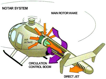
enter image description here

Also, many models of helicopters use ducted rear rotors, such as that shown below.
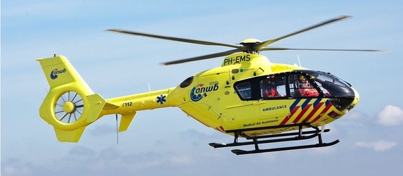
enter image description here

To counter the weight of the machine, and the torque of the main rotor of the helicopter, the reaction wheel, as I'm sure you know, would either have to be very heavy, or have a serious angular velocity, to achieve sufficient angular momentum and perform a useful stability restoring role.

The acid test for helicopter design is, in my opinion, do the military incorporate the ideas? If they don't, then there is probably a drawback to prevent further research.

EDIT The other answers regarding acceleration of the reaction wheel pretty much explain the line above, it's not just a drawback, it's impossible to implement. I should looked more into the mechanics of reaction wheels before answering. C'est la vie. END EDIT

$\endgroup$
11
  • 4
    $\begingroup$ Well, you have a heavy wheel, spinning very fast, then you need a heavy enclosure in case it " escapes ". I have seen the results of a steam engine balance wheel, when the governor mechanism failed, it took out the stone walls of the mill it was housed in $\endgroup$
    – user108787
    Commented Aug 13, 2016 at 23:46
  • 8
    $\begingroup$ "would either have to be very heavy, or have a serious angular velocity": These are tiny issues compared to the #1 concern of reaction wheels here: constant acceleration. $\endgroup$ Commented Aug 14, 2016 at 5:26
  • 1
    $\begingroup$ The key element of the notar (No Tail Rotor) design is use of a round tube, slotted boom that can be rotated. It utilizes the Coandă effect to control the helicopter. But rotating the tube (w/ slots) you can rotate the helicopter as desired. This is only augmented by a direct jet thruster and vertical stabilizers. $\endgroup$
    – zipzit
    Commented Aug 14, 2016 at 16:53
  • 1
    $\begingroup$ @zipzit I saw one on TV a few years ago, working it's way through a groups of trees and brushland. One less thing for the pilot to worry about. But I think ducted rear rotors have improved safety, l have not heard so much about the notar since. $\endgroup$
    – user108787
    Commented Aug 14, 2016 at 17:00
  • 2
    $\begingroup$ One possible reason for the down vote is that this is not an answer to the question asked. $\endgroup$
    – garyp
    Commented Aug 15, 2016 at 2:43
9
$\begingroup$

As far as the laws of physics are concerned, you could do it if every so often you use the stored angular momentum in the flywheel to quickly reverse the direction of the main rotor and then start building up angular momentum in the other direction.

Disadvantages: Oh boy, where to start? You need symmetric, and thus probably less efficient, rotor blades, and a more complex swash plate arrangement. You need a main shaft and blade attachments that can transfer insane torques to the rotor during the reversal maneuver. You need complex arrangements to allow the motor exert a finely controlled torque on the flywheel over a wide range of speeds. And it's going to be a very exciting ride if the lift disappears for half a second every so often while the rotor reverses.

$\endgroup$
2
  • 2
    $\begingroup$ This answer made me laugh out loud with the 'exciting ride' bit. $\endgroup$ Commented Aug 15, 2016 at 20:03
  • $\begingroup$ A heavy flywheel would also allow for some very interesting failure modes... $\endgroup$ Commented Aug 17, 2016 at 8:51
5
$\begingroup$

I consider this a very interesting idea, but clearly, you'd have to use the wheel as a gyroscope. Simply spinning up a wheel coaxial to the rotor would totally not achieve the goal, as elaborated by Rod Vance.

What you'd have to do instead is mount the wheel vertically. The wheel would spin at a high constant rate. Now, the rotor generates torque in a direction perpendicular to the gyroscope's angular momentum. Due to the way angular momentum adds up, the result would be a movement not so much in yaw, but in pitch/roll direction. You might now say this just replaces one problem with another, but not quite: unlike yaw, you can counteract pitch and roll with the main rotor alone, through the use of cyclic.

That alone would not be sufficient though: to really “transfer” torque between the directions, you need to actually change the rotation axis of the wheel. In other words, the helicopter would still spin, just slower! For some purposes this might actually be fine, at least in a drone helicopter. But for most applications, you would need a gimbal mechanism to change the wheel axis without spinning the helicopter body. This would make the construction quite a lot more complicated.

Quite likely, the whole thing is not practical, but it would definitely be interesting to try this concept out with a toy drone!

$\endgroup$
2
$\begingroup$

It is not possible to use a reaction wheel or any other means of resisting the torque by energy stored in a gyro as mentioned above. A mechanism like a rotating wheel or fly-wheel would work based on its angular inertia, J, which is directly proportional to its mass and the amount of torque it can save and deliver is not nealy enough for countering the main rotor's torque by even a few seconds for a mass of say 100 lbs wheel which is dead load. You need to accelerate it continuously because its available torque has already been spent to counter the rotor. Very soon you arrive at angular speeds which are beyond any reasonable technology.

Let's use the propeller of a Cessna 172 as an example of reaction wheel. It is approximately 50 lbs and 72 inch diameter (radius is exponentially related to J). At take-off or during some maneuvers it accelerates from 500 rpm to 2500 rpm in a couple of seconds and you'd expect a big torque that you have to deal with. True there is some amount of torque but even for me as a pilot who should anticipate it i don't feel much any thing. Just hear the roar of engine revving up.

The tail fan has easy controllable trust at small energy cost and can be geared to an automatic gearbox to work seamlessly with pitch and yaw controls and renders some self balancing inertia.

$\endgroup$
4
  • $\begingroup$ Is that a counter-argument to my answer, or only to the idea of a reaction wheel coaxial with the rotor, which was already thoroughly refuted in the previous answers? (It's quite possible that I've written rubbish, but I don't see how that follows from your argument.) $\endgroup$ Commented Aug 19, 2016 at 8:47
  • $\begingroup$ And FWIW, radius is most definitely not exponentially related to moment of inertia, the relation is “only” $J \propto r^4$, or perhaps $J \propto r^5$ if you account for extra robustness in a larger propeller. Though anyway I don't quite see what conclusion you take from that – does a larger moment of inertia not weaken your point? $\endgroup$ Commented Aug 19, 2016 at 8:51
  • $\begingroup$ Let's just assume a copter with a rotor diameter of 30 feet with 3000 lbs lift with a L/D ratio of 4.5. So each blade of rotor takes 3000/say 5/2=300 lbs drag force. Assuming it is imparted on the midspan of the blade we get 300*30/2=4500 lbs*ft torque. Very roughly any flywheel to counter this for even a few seconds no matter at what position is not practical. As far as the J of propeller a rough estimate of assuming the entire mass of one blade at center of gravity it will give J= 2m^2/2(.3R)^2. Point i am trying to make is the magnitude if torque of a helicopter is beyond any liftable gyro. $\endgroup$
    – kamran
    Commented Aug 19, 2016 at 13:44
  • $\begingroup$ By using the propeller of Cessna 172 I make the point that even a gyro as large as that effectively has minimal impact on a plane that is in the same order of mass as a light copter, 2000-2400 lbs.! $\endgroup$
    – kamran
    Commented Aug 19, 2016 at 17:03

Not the answer you're looking for? Browse other questions tagged or ask your own question.