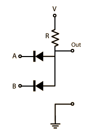
What is the role of the resistor in e.g. an AND gate like this one? :

One often sees lots of resistors in electric circuits, but I haven't really understood their role.
What is the role of the resistor in e.g. an AND gate like this one? :

One often sees lots of resistors in electric circuits, but I haven't really understood their role.
Resistors are generally used to dimension electrical devices to the ranges in voltage, current, time constants, what have you, that are needed. In this specific example the resistor is used to dimension the voltage drop in case one of the inputs has low voltage (lower than $V$), so that a current flows from $V$ to the input (it can only flow in this direction because of the way the diodes are connected).
Once a current $I$ flows, a drop of $V_{drop}=IR$ will drop across the resistor and lower the output voltage. This ensures the functionality as an AND gate. If both input voltages are high, no or only little current will flow, thus only a small voltage will drop keeping the output voltage high. If one of the too inputs has low voltage, the output oltage will drop.
In logical terms high voltages are logical 1s and low voltages are logical 0s.
To summarize $V$ is dimensioned to define what "low" and "high" voltages are. and $R$ is dimensioned to define how big the voltage drop is going to be.
The resistor provides the logic one when both inputs are high. As far as choosing a resistor, this is a matter of two contradictory requirements.
(1) You want the resistor to be low so that the circuit's propagation delay for low to high transitions is short. That is, you want it to drive a capacitive load (for example, wire plus parasitic capacitances) quickly. If the load is C and your time budget for the rise time delay is T, then you want $RC < T$ so pick $R < C/T$.
(2) You want the resistor to be high so that the circuit does not dump a lot of current through the diodes when the output is low. If the maximum current your weakest input can sink (at its low voltage level) is I, then you want $IR > V - V_d$ where $V_d$ is the voltage drop of the forward biased diode, so $R> (V-V_d)/I$.
This type of AND gate is somewhat primitive in that its low output voltage is a diode drop higher than its low voltage input. Therefore its output has a diode drop less noise immunity than its input (as compared to the same high voltage level). One can only do this so many times before running out of noise margin. This is why modern logic families have less primitive output stages.
I may be wrong, but I think the question is about the role of resistors in general, and it's just using the AND gate as an example.
If so, resistors may be used to achieve many objetives in a circuit from the logic point of view, but electrically they are indeed just passive components that resist the passing of current (see http://en.wikipedia.org/wiki/Electronic_component#Resistors).
Many times I've heard people who are rather new to electronics, like myself, wonder why is a resistor needed here or there. It all depends on the circuit. It could be like some answers pointed out, to pull-up (or down) the voltage, or just to limit the amount of current that flows at a certain point of a circuit (for example, to limit the amount of current a LED or any other component can withstand).
This last reason is of particular interest in practical applications, where you cannot afford to have current without limit flowing through a component, because it would most probably damage it beyond repair (it can even be dangerous and cause overheating, fire or explosion). This would be the use of a resistor to cope with a physical limitation of a component.
As a final comment, there are many types of resistors. Their resistance value can be fixed or variable, and among the variable-ones they can vary with light, heat, humidity and many other phenomena.
Let us consider an ideal situation where potential drop across diode is almost $0$ and designate the branch with resistor as 'branch $V$' .
Consider the situation when $A$ is at $V$ potential and $B$ at $0$.
There will be potential drop due to resistor $R$ in $V$ branch. Branch $A$ would be at comparatively higher potential, but diode would not allow current flow. So branch $A$ can be ignored.
Branch $B$ is at lower potential. So current flows through this branch from $V$ branch. Since $B$ is at $0$ V , 'out' branch and the end point of resistor $R$ are at $0$ V too.
If the resistor was absent, then there would be a short circuit since one end of $V$ brand would be at $0$ potential (due to branch $B$) and the other end would be at $V$ potential. Thus there would be a potential drop without any resistor to create the drop.