6
$\begingroup$

Thermoelectricity is, as I understand it, the difference in voltage between the hot and cold ends of two dissimilar materials. If two materials are connected at two different junctions, the hot junction will effectively liberate electrons which will flow to the cold junction, along with the heat.

All the diagrams of this I could find showed exactly two materials, connected at both the hot and cold ends. In order to have the hot side remain hot, and the cold remain cold, while transmitting the electricity, ideally a substance is desired that conducts electricity well, but heat poorly. This is the measure of quality. A good overview paper is: New Directions for Low-Dimensional Thermoelectric Materials by Dresselhaus et al.

"ZT= S2rT/j, where S, r, T, and j are, respectively, the Seebeck coefficient, electrical conductivity, temperature, and thermal conductivity"

Maximizing efficiency of a thermocouple is, in fact, a matter of finding materials that conduct heat poorly, while conducting electricity well. In practice, that's difficult, so in constructing nanomaterials to do so, they are trying to scatter phonons while not scattering electrons.

Questions:

  1. How do you make a series circuit with lots of thermocouples? Surely this must be done, yet when I draw a diagram, I can't come up with a way that doesn't look like two identical thermocouples are simply operating in opposing directions. This is answered below (and thanks), but note the answerer is incorrect about the need for thermal conductivity. Ideally, you want to insulate these things, and have as little heat as possible produce as much electricity as possible.

  2. In the diagram drawn by the answer, it shows a thermopile as a zig-zag connection of two materials between hot and cold. This makes perfect sense now that I see it, but then, does material A transport electrons from hot to cold, while material B transports them from cold to hot? I thought I intuitively understood the Seebeck effect as a liberation of electrons from the hot end, effectively by "shaking them loose" but it appears one material must be doing the reverse? I'm guessing this is similar to galvanic action, where one material wants an electron to complete a valence shell, and the other wants to give one away?

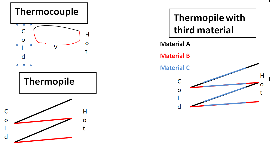
  3. I have now drawn a diagram showing a single thermocouple, a thermopile per the answer below, and my question, which is whether you can introduce a third material connecting the other two. I'm guessing you can, and that whatever its electropotential, since it's symmetric it should have no effect on the voltage of the thermopile other than its resistance. diagrams of thermopiles
$\endgroup$
1
  • 2
    $\begingroup$ Dov, I think it would be better if you ask these two questions separately. Edit one out of this post and then make it into a new post. You can link to this one to provide the context. $\endgroup$
    – David Z
    Commented Dec 2, 2011 at 16:06

2 Answers 2

4
$\begingroup$

In order to have the hot side remain hot, and the cold remain cold, while transmitting the electricity, ideally a substance is desired that conducts electricity well, but heat poorly.

The two ends are assumed to be connected to heat sources or sinks that maintain a constant temperature at those nodes. Hot electrons and cold electrons travel through the material at different rates, leading to a net flow of electric charge towards one end.

https://en.wikipedia.org/wiki/Seebeck_coefficient#Charge_carrier_diffusion

  1. How do you make a series circuit with lots of thermocouples? Surely this must be done, yet when I draw a diagram, I can't come up with a way that doesn't look like two identical thermocouples are simply operating in opposing directions.

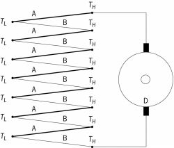
A series connection of thermocouples is called a "thermopile". It's connected like this: enter image description here

  1. Suppose you take two materials with an electropotential: Cobalt and Lithium. If you could make two junctions between them, one a cold, and one a hot, could you take a third material (copper) and use it to connect the two junctions? Does that ruin the thermoelectric effect?

Not sure what you're asking. You want to connect wires made of lithium, cobalt, and copper in parallel?

$\endgroup$
20
  • $\begingroup$ The question for a third metal arose from his problems to imagine a thermopile, I suppose. $\endgroup$
    – Georg
    Commented Dec 2, 2011 at 18:45
  • $\begingroup$ Thanks for clearing up my misconception, the diagram of a thermocouple always shows two junctions with both materials, and putting those in series is not possible. I will modify the original question to show a diagram of what I am asking about a third material $\endgroup$
    – Dov
    Commented Dec 4, 2011 at 11:42
  • $\begingroup$ This answer still implies that efficiency of a thermocouple is not based on good electrical conductivity, and poor thermal conductivity. This is simply not true, as can be seen in the paper I cited. It's true that you can maintain a constant temperature, but the point is to do so with MINIMAL ENERGY INPUT. The efficiency of current thermocouple generators is on the order of 6%, and with Zt of 4.0, it could be 30%. $\endgroup$
    – Dov
    Commented Dec 13, 2011 at 4:54
  • $\begingroup$ @Dov: I don't understand. The Seebeck effect is due to hot electrons traveling more poorly through the metal than the cold electrons traveling in the opposite direction. So the important property for determining the Seebeck coefficient for a material is that the thermal conductivity be energy dependent. $\endgroup$
    – endolith
    Commented Dec 13, 2011 at 15:26
  • $\begingroup$ @Dov: Wikipedia says "The efficiency with which a thermoelectric material can generate electrical power depends on several material properties, of which perhaps the most important is the [Seebeck coefficient]." "It is important to note that a material's Seebeck Coefficient is inversely related its carrier density. Therefore, insulators tend to have very high Seebeck coefficients, while metals have lower values due to their high carrier concentrations." Also: en.wikipedia.org/wiki/… $\endgroup$
    – endolith
    Commented Dec 13, 2011 at 15:30
0
$\begingroup$

I am writing this answer for several reasons. First, the current accepted answer is wrong. Second, that answer does not even answer the updated question involving a 3rd material. Third, it does not answer question 2.

1) The asker already answered his own question thanks to endolith's diagram even though the asker correctly pointed out that endolith is wrong in that "heat does flow well from one end to the other". No! A good thermoelectric material has a low thermal conductivity! This is a very active research topic nowadays: scientists are trying to figure out a lot of ways to decrease the lattice contribution to the thermal conductivity. What's more, endolith claims that generally one has surfaces of constant temperature in which the thermoelectric material is sandwhiched, and that these temperatures do not change. This is not true. In general one has a given heat source (could be the Sun, a motor, a Joule effect in wire) that heats a surface (the one of the hot part of the thermogenerator or thermopile for instance), but that temperature will of course be affected by the heat transfer toward the cold part. In other words, the choice of the thermoelectric materials will have an impact on the temperature difference! So a more correct remark would be "Heat flows from one end to the other" or "Heat flows from one end to the other although good thermoelectric materials have low thermal conductivity which impacts (negatively) on this heat flow".

2) Usually material A and B are made of n-type and p-type semiconductors, respectively. So the electrons are moving toward a different end, according to the material A or B, as you point out. In p-type materials, the charge carriers are holes which will gather at the cold side. In an n-type semiconductor, the electrons (they are the charge carriers) gather at the cold end. The result is that the voltage due to the Seebeck effect in each material adds up. So, to answer your question, yes, materials A and B are doing opposite thing and the reason is that they have opposite charge carriers.

3) You are wrong in claiming "since it's symmetric it should have no effect on the voltage of the thermopile other than its resistance." Unfortunately, if you do a setup like the one in your picture, notice that even though the Seebeck voltages in material C effectively cancel out (if there is an even number of these), you are also reducing the temperature difference in your materials A and material B, because they are now much shorter and do not have the whole temperature difference between the cold and hot sides. So the overall voltage will be reduced. You can however introduce a third material, and your conclusion would hold if it was placed along the cold and hot sides. And this is precisely what people do when building a thermoelectric generator (TEG) to link the p and n-type legs.

$\endgroup$

Your Answer

By clicking “Post Your Answer”, you agree to our terms of service and acknowledge you have read our privacy policy.

Not the answer you're looking for? Browse other questions tagged or ask your own question.