0
$\begingroup$

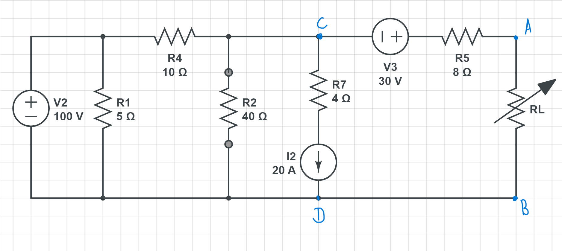
Consider this Circuit which is to be converted to Equivalent Thevenin's Circuit.

Full Circuit

Now I tried Solving this using two methods and got contradictory result. We need $V_{Th}$ and $R_{Th}$

$$R_{Th}= 8\Omega + 8\Omega = 16\Omega$$

Now Finding $V_{Th}$: -

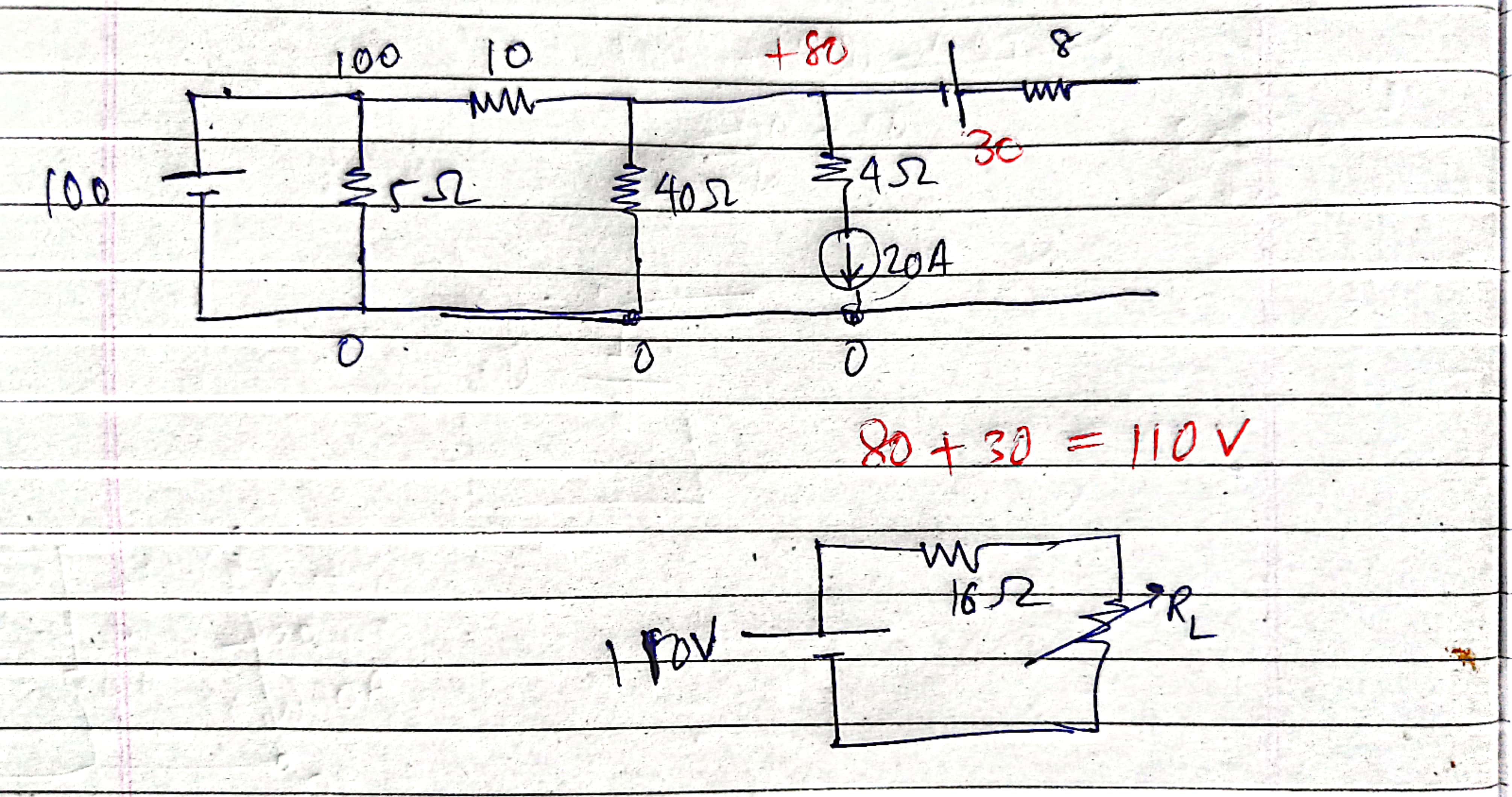
Method -$1$: - The current in $R_7$ branch is $20A$ and hence Voltage drop across the terminals $CD=$ $20A\times4\Omega = 80V$ and the direction of current points to fact that $V_C=80V$ and $V_D=0V$. Hence $V_{Th}=80+30=110V$

Thevenin's Circuit

Thevenin's Circuit

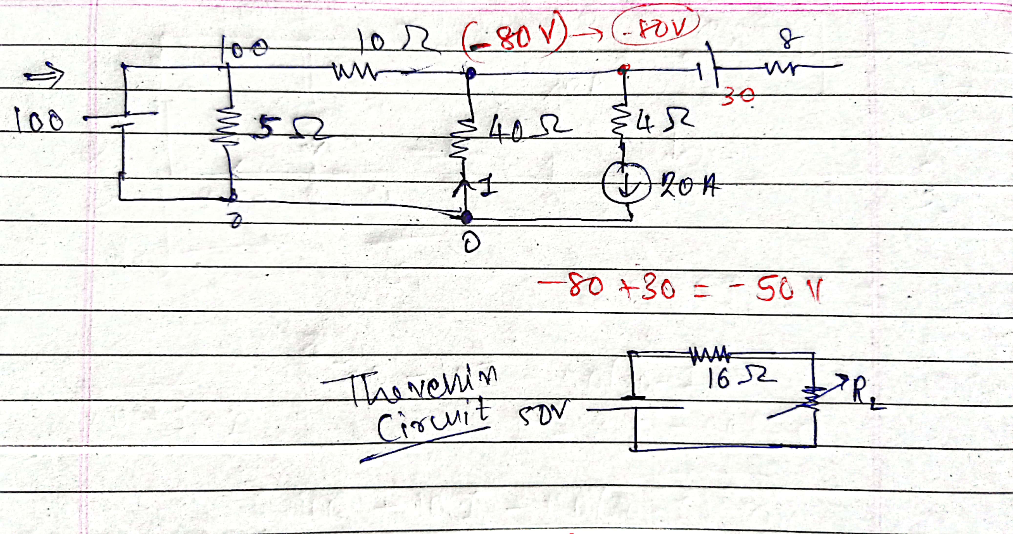
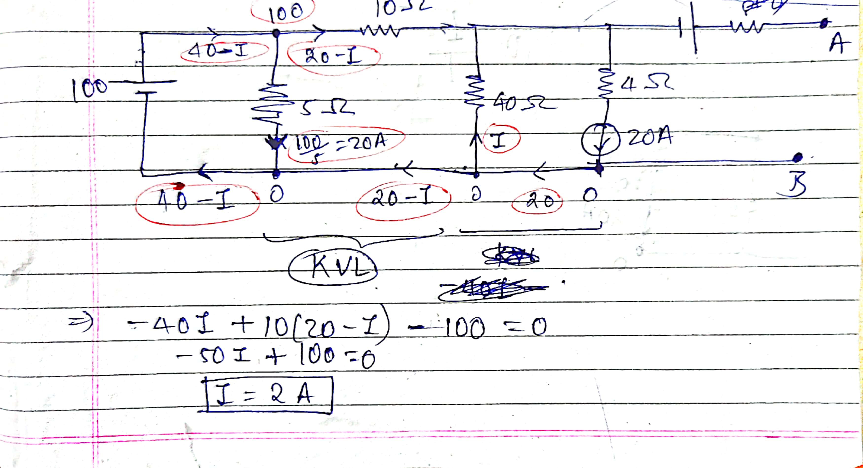
Method -$2$: - Using Circuit Laws (like KVL/KCL/Superposition) to solve the circuit when Load is open to get $V_{Th}$

Solution
Solution

Solution

You can see that the polarity of the $V_{Th}$ is coming opposite in both. Why?

$\endgroup$

4 Answers 4

1
$\begingroup$

You better recheck your methods. Your Thevinin resistance is correct. But both methods need to satisfy the basic relationship between the Thevenin resistance, Thevenin voltage (open circuit voltage) and the short circuit current across terminals A and B, which is

$$R_{Th}=\frac{V_{Th}}{I_{sc}}$$

Hope this helps.

$\endgroup$
1
$\begingroup$

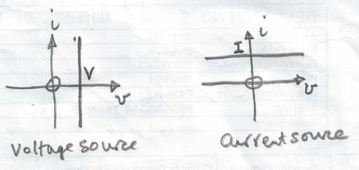
The $i-v$ characteristics of a voltage source and a current source are shown below.

enter image description here

Whatever the current magnitude or direction through a voltage source, the voltage across the source, $V$, is constant.
Whatever the potential difference across a voltage source, the current, $I$, delivered by the the source, $I$, is constant.

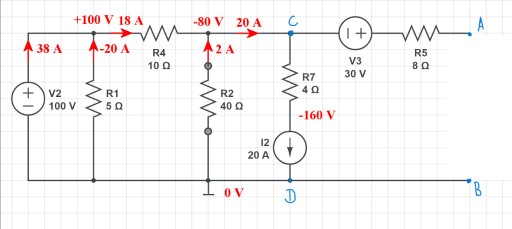
For the given circuit possibly the easiest way of finding the Thevenin voltage is first to find the potential of node $c$ relative to node $d$ which is taken as the reference node at $0\,\rm V$.

Using KCL and summing currents leaving node $C$ gives $\frac{C-100}{10} + \frac{C-0}{40}+20 = 0 \Rightarrow C=-80\,\rm V$.

Thus the currents and potentials are as in the circuit diagram below.
enter image description here

The Thevenin voltage is $-80 + 30 = -50 \,\rm V$.

Just as for a voltage source with the current though it determined by the connected circuit so the voltage across a current source is determined by the connected circuit.

As a check the electrical power produced by both the sources $(7000\,\rm W)$ should equal the electrical power dissipated in the resistors.

$\endgroup$
1
  • $\begingroup$ > "Just as for a voltage source with the current though it determined by the connected circuit so the voltage across a current source is determined by the connected circuit." This point clarified the doubt. Thanks $\endgroup$ Commented Oct 4 at 13:50
1
$\begingroup$

The current in $R_7$ branch is $20 \ \text{A}$ and hence voltage drop across the terminals $\text{CD}=$ $20 \ \text{A}\times4 \ \Omega = 80 \ \text{V}$

This is incorrect.

You are neglecting that there is also a voltage drop across the current source. So the voltage between $\text{C}$ and $\text{D}$ is equal to $80 \ \text{V}$ plus whatever is the drop across the current source. But you can't know what that voltage is without doing further analysis.

Since the current source changes its voltage however is necessary to produce its specified output current, it actually turns out that the $4 \ \Omega$ resistor is irrelevant to the circuit operation and can be replaced by a short circuit without affecting the node voltages or branch currents elsewhere in the circuit.

Two possible ways to proceed:

  1. Use superposition. First find the output voltage if only the voltage source is present and then with only the current source present. Add these two results to get the output voltage with both sources present.

  2. Treat the $20 \ \text{A}$ current source and $40 \ \Omega$ resistor as a Norton source. Transform it to a Thevenin equivalent. Combine it with the voltage source and $10 \ \Omega$ resistor (another Thevenin source --- the $5 \ \Omega$ resistor is also irrelevant as it is in parallel with a voltage source).

$\endgroup$
0
$\begingroup$

What I Understand : -

There's no way Method-2 can be wrong, hence there must be a flaw in Method-1.

So What I guess is that the Method one will only give correct answer when lets say $V_C=80V$ and as the voltage drop across resistor $=80V$ and by direction of $I_2$ the intermediate point between $C$ and $D$ has $0V$; and if and only if I consider that a $+160V$ is gained across the current source. Which can give $$V_{CD}=-80V$$ and gives $$V_{Th}=-50V$$

However I have some Doubts in this explanation:-

But how to find that Voltage gain across Current Source in general?

OR

If I am wrong with my guess than why does this contradiction happens, any other reason?

$\endgroup$

Your Answer

By clicking “Post Your Answer”, you agree to our terms of service and acknowledge you have read our privacy policy.

Not the answer you're looking for? Browse other questions tagged or ask your own question.