0
$\begingroup$

Electric waveguide basic reminders.

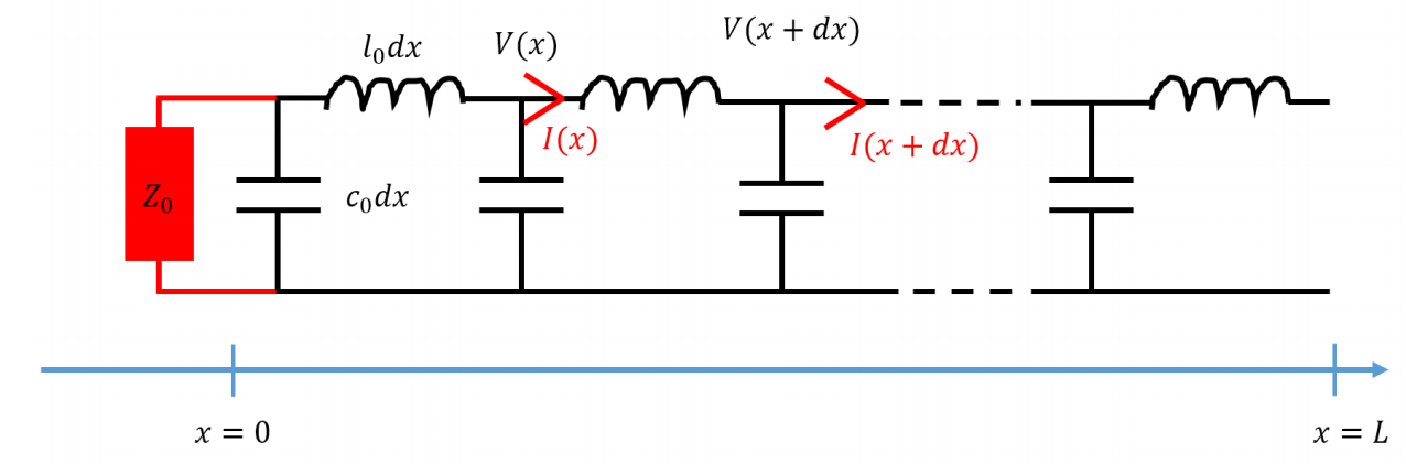
enter image description here

A lossless electric waveguide can be modelled as a succession of capacitance and inductance. Calling $c_0$ and $l_0$ the capacitance and inductance per unit length, we can see the waveguide as what is shown on the Figure above. The mass line is the bottom line (all voltage are defined with respect to it).

I added an impedance $Z_0$ at the end ($x=0$) of the waveguide. The impedance of the waveguide $Z_c$ is:

$$Z_c = \sqrt{l_0/c_0}$$

From this description, we can derive Telegraph equations. They tell us that we will have electric current and potential waves moving on the line. Basically, they imply:

$$ V_{\rightarrow}(x-ct)=Z_c I_{\rightarrow}(x-ct)$$ $$ V_{\leftarrow}(x+ct)=-Z_c I_{\leftarrow}(x+ct)$$

Up to my understanding, the voltage and current are always defined on the top line. Basically $I_{\rightarrow}(x-ct)$ or $I_{\leftarrow}(x+ct)$ represent the electrical current in $x$ at $t$ on the positive (upper) line of my drawing. The voltage are the voltage difference between the positive (upper) line and the mass (bottom) line.

Where $\rightarrow$ are the wave propagating toward $x>0$ ($x<0$ for $\leftarrow)$. The velocity of the waves is $c=\frac{1}{\sqrt{l_0 c_0}}$

The total voltage and current at a given point $(x,t)$ are thus the sum of forward and backward waves:

$$V(x,t)=V_{\rightarrow}(x-ct)+V_{\leftarrow}(x+ct)$$ $$I(x,t)=I_{\rightarrow}(x-ct)+I_{\leftarrow}(x+ct)$$

Now, what I do is to inject a voltage in $x=L$, it will propagate inside the waveguide until reaching $x=0$. Here the impedance $Z_0$ will describe what happens: what is the reflected waves.

We just apply Ohm law in $x=0$, which tell us:

$$V(0,t)=-Z_0 I(0,t)$$

After few calculations, it implies:

$$ \frac{V_{\leftarrow}(0,t)}{V_{\rightarrow}(0,t)}=r=\frac{Z_0-Z_c}{Z_0+Z_c}$$

My question

Let's assume I plug to a voltage generator a closed waveguide, like on the following figure (the wire goes out from the $+$ and goes back on the $-$. I assume the length of the wire to be long enough so that we can see propagation phenomenon.

enter image description here

Here the voltage and current I will inject will just follow the waveguide and there will have no reflection. It will go out from the $+$ pole of the generator, propagate, and go back on the $-$ of the generator.

My question is: how can I understand this physics from the general formalism above. Indeed in a way we should say that it corresponds to $Z_0=0$ (because no charge is plugged on the circuit), but this case implies a reflected wave, indeed I will have:

$$V_{\rightarrow}(0,t)=-V_{\leftarrow}(0,t)$$ $$I_{\rightarrow}(0,t)=I_{\leftarrow}(0,t)$$

How to describe the physics of my generator connected to a closed wire in term of the general description given above ?

$\endgroup$

2 Answers 2

1
$\begingroup$

At $x=0$ you are forcing a boundary condition of a perfect electric conductor (PEC) on the propagating waves. PEC means that the tangential E field is assumed zero, here along the shunt wire meaning the voltage drop across the shunt is zero because it is also assumed that the length of the shunt is much shorter than the wavelength, hence there is no voltage variation across it. If the length of the wire were longer than a wavelength then you could have a complicated and "parasitic" propagation along the shunt, one that your single TEM mode propagation along the transmission line could not handle, instead you would have to include other TE and TM modes propagating along the transmission line if you wanted to analyze that more complicated situation.

$\endgroup$
10
  • $\begingroup$ Thank you for your answer. Does that mean that a wire going from the + to the - of my generator is not equivalent to my first figure ? In this first figure I assume that in x=0 there is absolutely no voltage drop, thus "better" material than the rest of the wire which is composed of inductance and capacitances ? Is it how I should understand your answer ? $\endgroup$
    – StarBucK
    Commented May 8, 2020 at 12:45
  • $\begingroup$ Thus the physics corresponding to my second graph would correspond to an impedance Z0 that would somehow match the inductance and capacitance of my waveguide. $\endgroup$
    – StarBucK
    Commented May 8, 2020 at 12:48
  • $\begingroup$ Think of a finite segment (with both ends) of your infinite $LC$ ladder, and let $\Delta x \approx 0 (dx)$ be small and also finite altogether a zillion elements; now short the left end and put a generator on the right end, directly shunting $c_0$. In a practical situation losing a single one of the zillion identical but tiny caps cannot make any difference, right? $Z_0=\sqrt{\frac{\ell}{c}}$ $\endgroup$
    – hyportnex
    Commented May 8, 2020 at 12:50
  • $\begingroup$ Then I am not sure to understand your answer. I edited my question part to make it more precise. If you can answer this I think my problem will be solved. Thanks again for your time. $\endgroup$
    – StarBucK
    Commented May 8, 2020 at 13:36
  • $\begingroup$ you wrote: "Here the voltage and current I will inject will just follow the waveguide and there will have no reflection. It will go out from the + pole of the generator, propagate, and go back on the − of the generator." Not really, neither the current nor the voltage does that, instead they "leave" both the + and the - end of the source simultaneously. $\endgroup$
    – hyportnex
    Commented May 8, 2020 at 15:24
0
$\begingroup$

Why do you suddenly neglect the capitance and inductance? Replace the impedante with a "normal wire" in your sketch. That might clear the picture

$\endgroup$
1
  • $\begingroup$ My drawing without the capacitance and inductance is to emphasize the fact that on the lab level you basically have a single wire going outside of the generator and coming back. To really emphasize that $x=0$ is not particular at all, it is a point like many others. With the other drawing it might confuse the reader that would think that this point is very specific (but experimentally it is not !) $\endgroup$
    – StarBucK
    Commented May 8, 2020 at 12:30

Your Answer

By clicking “Post Your Answer”, you agree to our terms of service and acknowledge you have read our privacy policy.

Not the answer you're looking for? Browse other questions tagged or ask your own question.