Your question seems to contain two parts.
First, you're asking how to set up the equations of motion for this coupled system.
Second, you are asking how to use symmetry considerations to find the normal modes and frequencies.
Let's first answer the bit about symmetry first
Normal modes - symmetry
Your observation about the reflection symmetry is spot on.
In general, the normal modes of the coupled system are linear combinations of the modes of the uncoupled system.
As you pointed out, the system has a reflection symmetry.
This means that the modes of the coupled system also have reflection symmetry, although the modes may be even or odd under that symmetry.
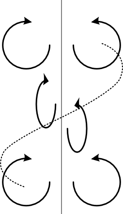
The mode with even reflection symmetry is the one where as one circuit's current is flowing clockwise, the other circuit's current is flowing counterclockwise.
You can see that this mode has even reflection symmetry by imagining picking up the diagram and flipping it left to right, as shown in the attached figure.

From these considerations you should be able to figure out what the odd mode looks like.
Do you know how to get the frequencies from here?
Equations of motion
Here we show how to write down equations of motion when mutual inductance is involved.
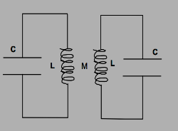
Let the left circuit be called #1 and the right circuit be called #2.
Denote the inductance and capacitance of circuit #1 as $L_1$ and $C_1$, and similarly for circuit #2.
Denote by $V_1$ and $I_1$ the voltage across and current through $L_1$, and similarly for $V_2$ and $I_2$.
A mutual inductance means that the two inductors share flux.
In particular, the flux in $L_1$ due to the current $I_2$ is
$$\Phi_{1,2} = M I_2$$.
This is just the definition of mutual inductance.
This flux adds to the self flux $\Phi_{1,1}$ of circuit #1.
Therefore, we have
$$\Phi_1 = \Phi_{1,1} + \Phi_{1,2} = L_1 I_1 + M I_2$$
Differentiate both sides to get
$$\dot{\Phi}_1 = - L_1 \ddot{Q}_1 - M \ddot{Q}_2 $$
where here we used $I_1 = -Q_1$ which is correct because current flowing downward through each inductor is flowing away from the corresponding capacitor.
You learned that the time rate of change in flux of an inductor gives the voltage across it: $\dot{\Phi} = V$.
Using this fact gives us
$$V_1 = -L_1 \ddot{Q}_1 - M \ddot{Q}_2 . $$
The voltage across the inductor and capacitor are the same because they're wired in parallel. Therefore, $V_1 = Q_1 / C_1$ by the definition of capacitance, resulting in
$$
\begin{align}
\omega_1^2 Q_1 &= - \ddot{Q}_1 - (M/L_1) \ddot{Q}_2 \\
\text{and by symmetry} \qquad
\omega_2^2 Q_2 &= - \ddot{Q}_2 - (M/L_2) \ddot{Q}_1
\end{align}
$$
where $\omega_i \equiv 1/\sqrt{L_i C_i}$.
Are these equations reasonable?
If $M=0$ then we have
$$\omega_1^2 Q_1 = -\ddot{Q}_1 \qquad \text{and} \qquad \omega_2^2 Q_2 = - \ddot{Q}_2$$
which is precisely what you expect for uncoupled oscillators.
Therefore, our equations of motion are probably correct.


