2
$\begingroup$

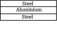
I’m working on a problem involving two steel rods and one aluminum rod of equal length and cross-section rigidly joined at their ends. And the overall rod, made by joining them is overall free. When the system is heated, I’m trying to calculate the final length of the system using the generalized form of Hooke’s law that's mentioned here:

This is the situation

It's assumed that the system is under no initial tension, and has no change in area, even after expansion, so everything can be assumed to be purely 1-dimensional.

I started to apply the law: $\sigma = Y(\epsilon - \alpha dT)$ for both the rods. I also assumed that the steel rods would want to expand more, or simply $\alpha_s > \alpha_a$

Then, the force, or stress, that aluminium would be under has to be twice the force that either steel rod is under (because there are two rods applying force on the aluminium rod).

So, now, essentially, $2Y_s(\epsilon_s - \alpha_s dT) = Y_a(\epsilon_a - \alpha_a dT)$

Also, because the two rods are tightly clamped to each other, then, the strain on both the rods should be equal, and then finally equating the strain, from which I can find the final length, I get the answer,

$\epsilon = \frac{2Y_s\alpha_s - Y_a\alpha_a}{2Y_s - Y_a}$

Now, the actual answer suggests that instead of subtraction both the terms in the numerator and the denominator have to be added. Which makes me doubtful if there has to be some sort of direction, or sign associated with the stress or the strain. Since, the actual length of both the rods increases, there can't be negative strain. But, the forces in the steel rods are opposite to the change in length. But, stress doesn't have anything to do with direction, or does it? (Is this where I'm wrong?)

How to handle sign conventions in stress and strain for systems involving compression and tension? If for two rods, one under compressive stress, and one under expanding stress, and both under the same overall change in length (the overall strain), should the signs of stress be different?

Whether my approach to equating the strains is conceptually correct?

This seems like homework, but it actually isn't. I had to share my work because giving context was important.

$\endgroup$
6
  • $\begingroup$ Is your system rigidly clamped on the top and bottom, meaning on the two steel samples? $\endgroup$ Commented Nov 18 at 1:23
  • $\begingroup$ No. Essentially it's just a free rod. $\endgroup$
    – WebbWayne
    Commented Nov 18 at 3:10
  • $\begingroup$ You’ve written a stress relation without looking at the underlying forces that causes these stresses. These forces must be equal and opposite between regions. I don’t understand the comment “stress doesn't have anything to do with direction. $\endgroup$ Commented Nov 18 at 13:05
  • $\begingroup$ I've done some work on the question myself now, and now basically I want to know this: "Because the iron rods expand outwards, but the forces on them that causes that stress are inwards, should I apply opposite signs for the LHS, or the RHS in the equation?" Basically if the stress is in opposite direction to the strain, is there a negative factor in the equation as to say the stress has a direction. $\endgroup$
    – WebbWayne
    Commented Nov 18 at 14:00
  • $\begingroup$ I am missing how the rods are joined. Where is the length and where is the radial direction or directions? Are these three rods that run lengthwise left-to-right, and we are viewing a side view? Are these three rods actually three flat plates, and we are viewing the end view where the three plates extend (in some length) into the plane of the picture? The formulations depend on a having better specifications for the physical geometry of the system. $\endgroup$ Commented Nov 19 at 4:56

1 Answer 1

0
$\begingroup$

The relative thermal expansion (thermal strain) of each rod/plate individually is defined by the linear thermal expansion coefficient $ \Delta l / l_o = \alpha \Delta T$. Under thermal treatment, the rods will expand transversely along their axes as well as radially. We ignore the radial expansion for the first analysis.

Assume that the rods are joined perfectly along their length. Assume that they have different thermal expansion coefficients. They each will experience a shear stress $\tau$ at their connecting boundaries. The shear stress is a result of the different relative thermal expansions. The central (aluminum A) rod will experience shear on two sides, while the outer (steel S) rods will experience shear each only on its connecting side.

The net relative difference in thermal expansion experienced at the aluminum rod surface is

$$\frac{\Delta l_T}{l_o} = (\alpha_S - \alpha_A) \Delta T $$

When steel expands more ($\alpha_S > \alpha_A$), it pulls in tension shear on the aluminum. When aluminum expands more, it is pulled back in compression shear by the steel.

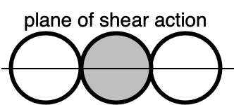
The rods are circular in cross section and are joined only at contact points in their radii. This configuration leads can be modeled as a plane where the shear forces act.

plane of shear action

To first order, the surface shear stress $\tau$ on the aluminum (central rod) is induced by the net thermal shear displacement $\Delta l_T$. One model assumption is that the shear acts over the half-width (radius) of the rod (because the system is fortuitously symmetrical).

$$\tau = G\ \frac{\Delta l_T}{r_o} = G\ (\alpha_S - \alpha_A)\ \frac{l_o}{r_o}\ \Delta T $$

In this equation, $G$ is the shear modulus. For isotropic materials, the shear modulus is related to the Young's modulus $E$ as $E = 2G(1 + \nu)$, where $\nu$ is the Poisson ratio. The more appropriate behavior is that the shear acts only in a boundary region at the joining boundary of the two pieces.

Consider the extreme case of rods with nearly infinitely large diameter. The left-most and right-most ends of the steel rods are expanded only to their normal thermal expansion $\Delta l/l_o = \alpha_S \Delta T$ because they are in an unconstrained expansion and feel no shear stress. Both contact points between steel and aluminum are expanded to a net $\Delta l_T/l_o$ as the difference between the two thermal expansions. Both contact points feel shear, either compressive or tensile. Finally, the center of the aluminum rod is expanded only to its normal thermal expansion $\Delta l/l_o = \alpha_A \Delta T$ because it also expands freely without applied shear. In the opposing extreme case where the rods are essentially only one atom in diameter, the shear moves the atomically wide rod as though it is also being acted on by a normal force even though the rod itself is not.

In summary, the system cannot be modeled as through the two shear stresses on the two opposing points contacting the central rod resolve to a normal stress throughout the entire central rod, thus shrinking or expanding the entire rod uniformly. The shear stresses do not resolve in this manner. The rod deformation is non-uniform across the plane of shear as well as over the radial paths outside the plane of shear.

$\endgroup$
2
  • $\begingroup$ The usual assumption in systems like this is that the inter-laminar shear is present only in narrow regions at the two ends. These regions are on the order of the layer thicknesses. $\endgroup$ Commented Nov 21 at 12:00
  • $\begingroup$ @ChetMiller duly noted thank you $\endgroup$ Commented Nov 21 at 14:56

Your Answer

By clicking “Post Your Answer”, you agree to our terms of service and acknowledge you have read our privacy policy.

Not the answer you're looking for? Browse other questions tagged or ask your own question.