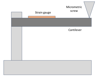
I intend to use a cantilever beam to calibrate a strain gauge, in a setup similar to the picture.
My idea is to introduce a small known vertical displacement $\delta$ on one side of the cantilever through a micrometric screw and to compute the strain in the upper surface of the cantilever to compare it with the strain gauge's resistance variation.
I have found that the deflection at any point $x$ along the span of an end-loaded cantilever beam can be calculated by:
$$y\left(x\right)=\frac{F}{6EI}x^2\left(x-3L\right) \tag{1}$$
with $F$ a force acting on the tipo of the beam, $L$ the span of the beam, $E$ the modulus of elasticity, and $I$ the area moment of inertia of the beam's cross-section. So, to find the variation in length, I initially thought naively about finding the arc length integrating the profile $y(x)$ of the beam:
$$s = \int _0 ^L \sqrt{1+(y'(x))^2}dx \tag{2}$$$$s = \int _0 ^{\tilde{L}} \sqrt{1+(y'(x))^2}dx \tag{2}$$
However, I am unsure about this approach, since, as I understand it, equation (1) would give the deflection of the neutral axis of the beam, and it wouldn't account for the strains that are present in the upper and lower surfaces due to stresses present in those surfaces. Moreover, the upper limit of the integral, $\tilde{L}$, is unknown.
Therefore, what could be an approach to compute the strain in the external surfaces of the beam from the displacement $\delta$ inon the free side?

